
EMI shielded module

Inactive Publication Date: 2003-09-11
COMMSCOPE TECH LLC +1
View PDF9 Cites 21 Cited by
  • Summary
  • Abstract
  • Description
  • Claims
  • Application Information

AI Technical Summary

Benefits of technology

[0004] Typically, a module such as a combiner has receptacles mounted on a printed circuit board. Terminals of a plug extend into a receptacle and are electrically coupled to the circuit board by electrical components that are all located on the same side of the circuit board. In particular, electrical components communicate with the receptacle and electrically couple terminals of a plug to the proper layer of the circuit board using vias, for example, if necessary. This style of mounting increases the amount of signal radiating around the electrical components causing cross talk in adjacent circuits. Also, because the leads of the electrical components are inductive, special circuit designs are used to compensate.

Problems solved by technology

This style of mounting increases the amount of signal radiating around the electrical components causing cross talk in adjacent circuits.
Such radiation interferes with the operation of the headend.

Method used


Image

  • EMI shielded module
  • EMI shielded module
  • EMI shielded module

Examples


Embodiment Construction

[0022] Referring now to the drawing figures in which identical elements are numbered identically throughout, a description of the preferred embodiments of the present invention will now be provided.

[0023] It will be appreciated that the disclosed RF components are merely examples of the type of equipment to which the various aspects of the present invention are applicable. Thus, it will also be appreciated that the various aspects of the present invention are applicable to types of RF components other than those specifically shown. Further, the present invention has general applicability in the telecommunications field, and is not limited to RF applications.

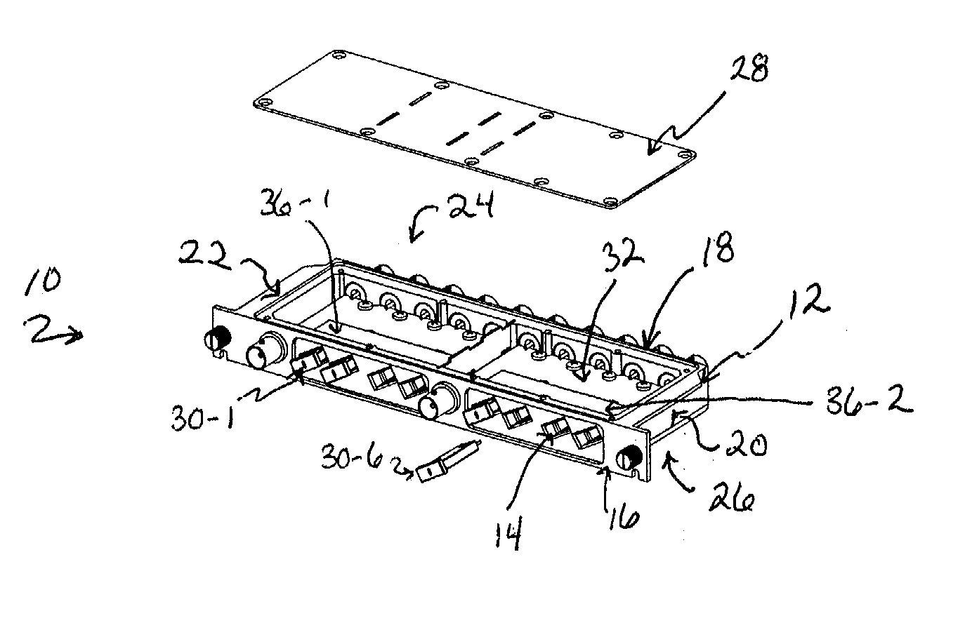
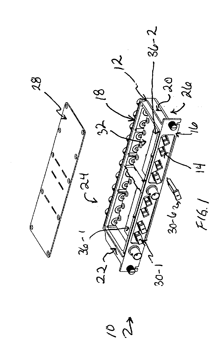
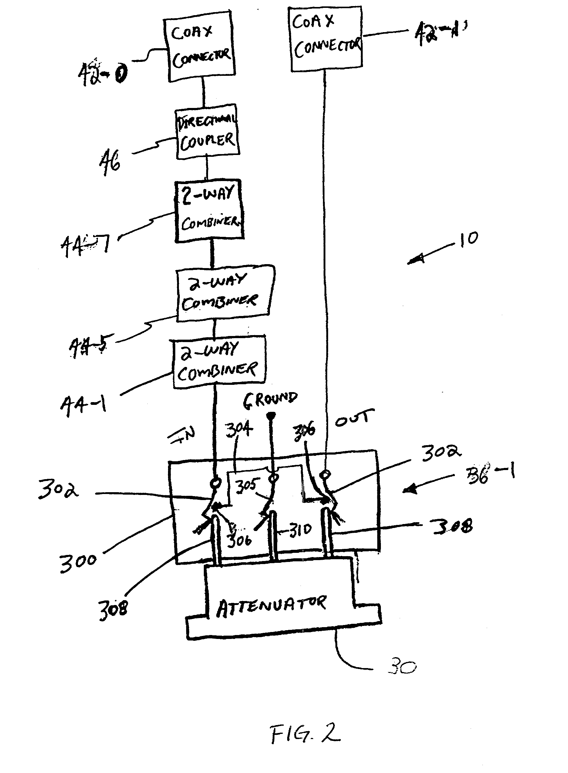
[0024] FIG. 1 is a perspective view of an eight port RF combiner module 10 according to a preferred embodiment of the present invention with a top plate removed. The module 10 includes a housing 12. The housing 12 includes a front 16 and a back 18 opposite the front 16. The front and back 16, 18 are joined by a pair of sides 20 a...


PUM


Abstract

A module for containing a circuit is provided that attenuates emitted signals without the use of a cover. The module includes a housing and a receptacle. The housing has a front having a certain thickness and the receptacle is accessible from the front of the housing. The receptacle is shaped to receive a circuit component and forms a waveguide.

Description

Background of the Invention[0001] In the telecommunications industry and more particularly in the video transmission industry, signals (e.g., 5 MHz to 1 GHz) are carried over coax conductors from a headend to customers. At the headend of the systems, numerous signals are manipulated to achieve a wide variety of functions and objectives. For example, signals carried on numerous coax cables may be combined onto a single coax conductor. Similarly, a signal on a main coax conductor may be divided into a plurality of signals carried on branch coax conductors.[0002] In addition to combining, splitting, diverting or adding signals, the headend will also include a module for modifying signals. For example, in order to adequately tune the system, it may be desirable to provide attenuators or the like to attenuate a signal to a desired level. Further, as a broadband RF signal is carried over a length of cable, the high frequency range of the signal may be attenuated more than a low frequency ...

Claims


Application Information

Patent Timeline
IPC IPC(8): H01R13/447H01R12/16H01R24/38H01R24/52H05K1/02H05K1/14H05K9/00
CPCH01R13/447H05K9/0062H05K1/141H05K1/0237
Inventor LOEFFELHOLZ, TODDBLUBAND, ZAKHCZYSCON, JOEMCCLELLAN, TERRYPODELL, ALLEN
Owner COMMSCOPE TECH LLC
Learn More