Integrated pool heater control system

a control system and integrated technology, applied in swimming pools, vehicle heating/cooling devices, transportation and packaging, etc., can solve problems such as complex final installation

Inactive Publication Date: 2003-09-11
DYMAS FUNDING COMPANY
View PDF16 Cites 48 Cited by
  • Summary
  • Abstract
  • Description
  • Claims
  • Application Information

AI Technical Summary

Benefits of technology

0004] An integrated heater and control system for a pool or spa is described, and includes a housing structure. A heater assembly includes a burner and a heat exchanger, and is disposed within the housing structure. An electronic control system is mounted within or on the

Problems solved by technology

This is expensive and time consuming and re

Method used


Image

  • Integrated pool heater control system
  • Integrated pool heater control system
  • Integrated pool heater control system

Examples


Embodiment Construction

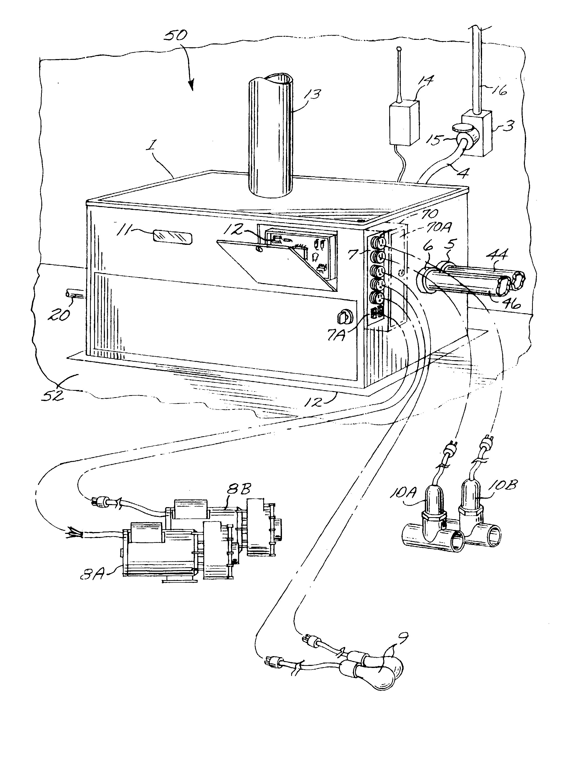
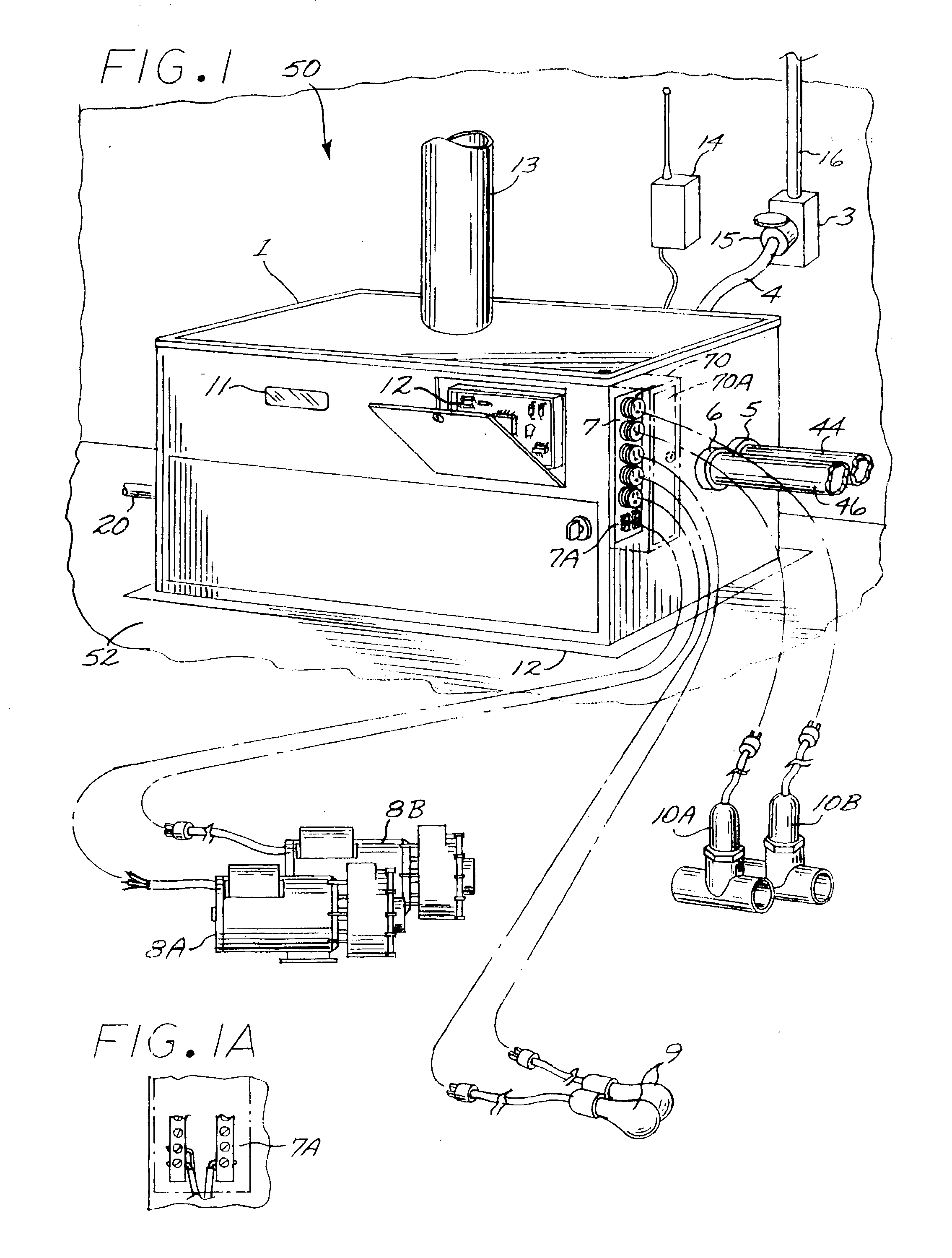
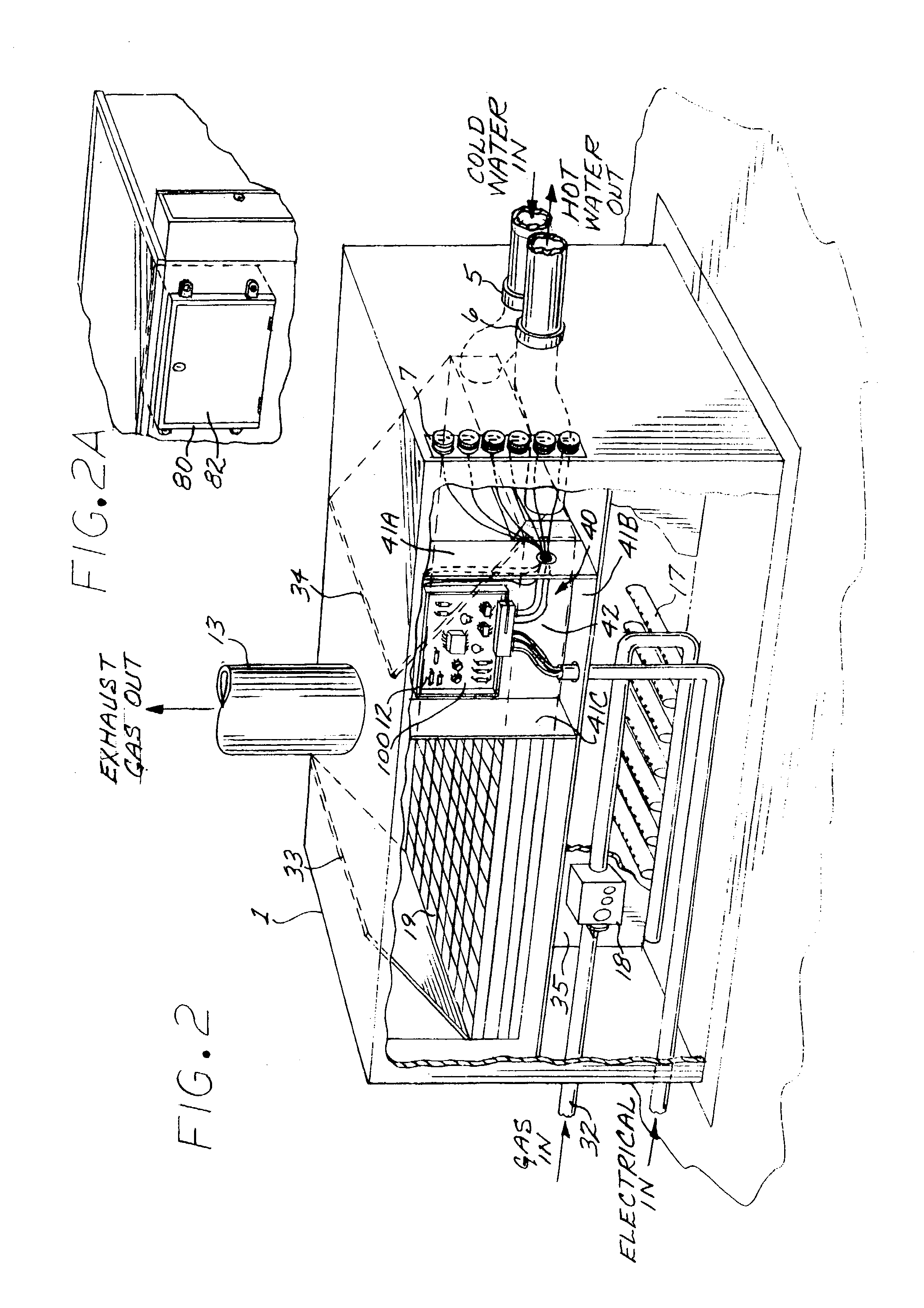
[0012] In an exemplary embodiment of a pool heater system in accordance with aspects of this invention, the pool heater, which is typically, but not necessarily, gas fired, is usually of some generous size and proportion, and engineered to sit directly on a hard surface, such as a concrete slab. In addition, the heater is usually engineered to withstand direct rain, as found in an outside installation. In addition, the stable construction of the heater is suitable for the mounting and enclosing of electrical control components.

[0013] Where a pool is equipped with a heater, there has also been the difficulty of finding appropriate places to connect various temperature sensors, water parameter probes and other sensors. In addition, these connections, if not properly made, can result in improper operation of the pool heater and associated equipment. Performing these installations and connections in the factory insures reliable and proper operation. In addition, simple connection points...


PUM


Abstract

An integrated heater and control system for a pool or spa is described, and includes a housing structure. A heater assembly includes a burner and a heat exchanger, and is disposed within the housing structure. An electronic control system is mounted within or on the housing structure for controlling the heater assembly and pool or spa functions. In one exemplary embodiment, the control system distributes line voltage power and low voltage control signals to one or more external devices, such as a heater circulation pump and a valve.

Description

[0001] This application claims priority from provisional application serial No. 60 / 362,205, filed Mar. 6, 2002.BACKGROUND OF THE DISCLOSURE[0002] In conventional residential pool systems, the pool equipment generally includes a heater pump, a filter, and a control system. Generally, the control system is installed on some type of hard surface, such as an adjacent wall, or on some type of supports specifically constructed to provide a rigid mounting point. The rigid mounting points, whether a wall or a newly installed support, must provide enough elevation to hold the electrical contacts above the ground, protecting them from flooding water, and placing access point within easy reach of service.[0003] Generally, an adjacent electrical service box is provided in which several circuit breakers are provided. These circuit breakers are then electrically connected to relays in the control system housing via conduit. Additional conduits are then installed from the control system housing to...

Claims


Application Information

Patent Timeline
IPC IPC(8): E04H4/12
CPCE04H4/129
Inventor CLINE, DAVID J.
Owner DYMAS FUNDING COMPANY
Why Eureka
Try Eureka