Method for synchronizing digital signals

a digital signal and synchronization technology, applied in the field of synchronizing digital signals, can solve the problems of not being able to achieve accurate synchronization (to within one image), expensive implementation, etc., and achieve the effect of accurate time synchronization and simple implementation

Active Publication Date: 2003-09-25
TELEDIFFUSION DE FRANCE SA
View PDF17 Cites 21 Cited by
  • Summary
  • Abstract
  • Description
  • Claims
  • Application Information

AI Technical Summary

Benefits of technology

0023] The method of the invention seeks to provide accurate time synchronization while being simple to implement and without introducing any modification in the two signals that are to be modified. The main function of the method consists in evaluating the exact phase offset between the two signals. Thereafter, knowledge of this offset is used to correct the lack of synchronization.

Problems solved by technology

Amongst existing approaches, the approach based exclusively on correlation is expensive to implement.
Furthermore, it does not make it possible to achieve accurate synchronization (to within one image) merely on the basis of the time references present in the signals.

Method used


Image

  • Method for synchronizing digital signals
  • Method for synchronizing digital signals
  • Method for synchronizing digital signals

Examples


Embodiment Construction

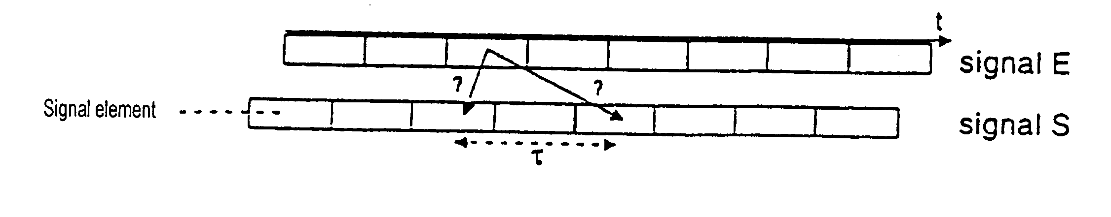
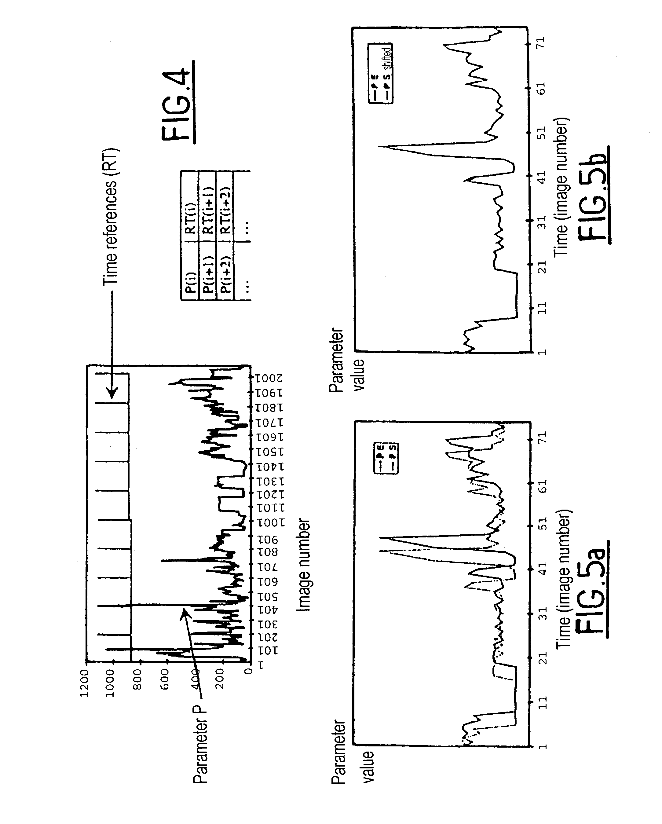
[0051] The first step of the method of the invention is preliminary synchronization making use of time references.

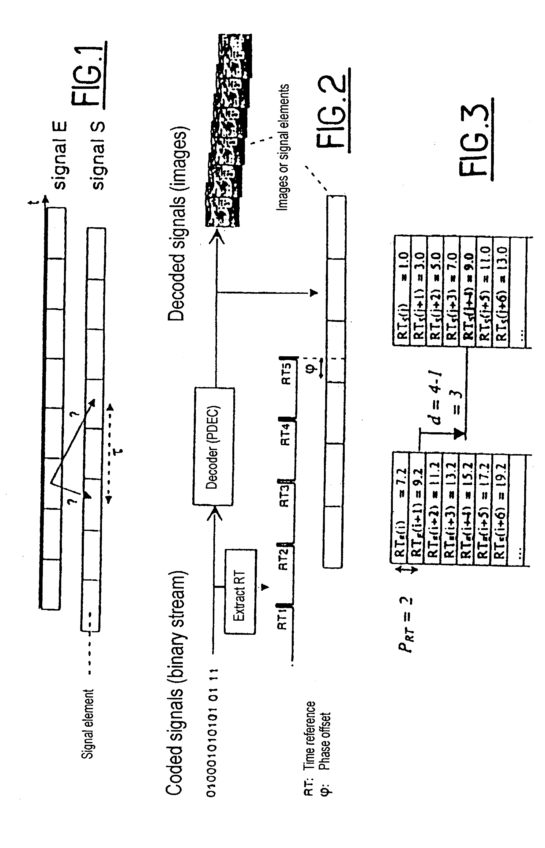
[0052] This first step makes use of two series of time references RT.sub.E and RT.sub.S coming from two sequences E and S respectively that are to be synchronized. It consists, for a value RT.sub.S(j) of the series RT.sub.S, in seeking the closest value in the series RT.sub.E(i), and the offset to be applied to one of the series in order to synchronize them. For this purpose, two approaches are proposed:

[0053] A "exhaustive" search:

[0054] A value RT.sub.E(i) of the series RT.sub.E is selected. If the value RT.sub.S(j) of the series RT.sub.Sis greater than RT.sub.E(i), then the sequence S is in advance relative to the sequence E. It is therefore necessary to retard the sequence RT.sub.S by decrementing j until this advance disappears. Conversely, if the value RT.sub.S(j) of the series RT.sub.S is smaller than RT.sub.E(i), then j is incremented.

[0055] IF RT.sub.S(j=1)>RT.s...


PUM


Abstract

The invention relates to a method of synchronizing first and second digital signals presenting digital elements to be put into correspondence, on the basis of time references. The method implementing: a) preliminary synchronization of the two digital signals using time references, by putting time references recognized as having the same value in the first and second digital signals into correspondence; and b) fine synchronization on the basis of a characteristic parameter obtained from the binary streams of said digital elements, and computed for each of said first and second digital signals.

Description

[0001] The introduction of digital technology into television in particular opens up new perspectives in the field of broadcasting audiovisual signals. The use of datarate-reducing encoding techniques such as the method defined in ISO / CEI standard 13918 MPEG-2, and digital modulation techniques make it possible in particular to offer a larger number of services to the end user.[0002] Nevertheless, the signals restored after decoding are no longer identical to the original signals. The constraints imposed in terms of data rate or bandwidth available for transmission and the content of the signal imply that characteristic kinds of degradation appear at low data rate or under difficult transmission conditions.[0003] In order to monitor signal quality, most measuring methods need to compare received signals (or characteristics of such signals) with transmitted signals (or with characteristics of transmitted signals). Consequently, a prior condition for monitoring quality is to be able t...

Claims


Application Information

Patent Timeline
Patent Type & Authority Applications(United States)
IPC IPC(8): H04N5/04H04N5/44H04N17/00
CPCH04N5/04H04N5/4401H04N21/4302H04N21/242H04N17/004H04N21/426
Inventor BAINA, JAMALBRETILLON, PIERREGOUDEZEUNE, GABRIELMASSE, DENIS
Owner TELEDIFFUSION DE FRANCE SA
Why Eureka
Try Eureka