Disposable illuminated fishing lure

a technology of illuminated lures and fishing rods, which is applied in the field of illuminated fishing rods, can solve the problems of clumsy prior art devices, dangerous to operators, and devices that contain hooks, and can be hazardous to handl

Inactive Publication Date: 2003-10-02
CALAK CHARLES THOMAS JR +1
View PDF0 Cites 20 Cited by
  • Summary
  • Abstract
  • Description
  • Claims
  • Application Information

AI Technical Summary

Benefits of technology

0006] It is the object of this invention to provide a lure whose en

Problems solved by technology

Prior art devises are typically clumsy, requiring disassembly to remove the battery in order to turn on and shut off the light source.
They can also be dangerous to the operator by requiring the jarring of the device for the battery to make contact with the light source, or by

Method used


Image

  • Disposable illuminated fishing lure
  • Disposable illuminated fishing lure

Examples


Embodiment Construction

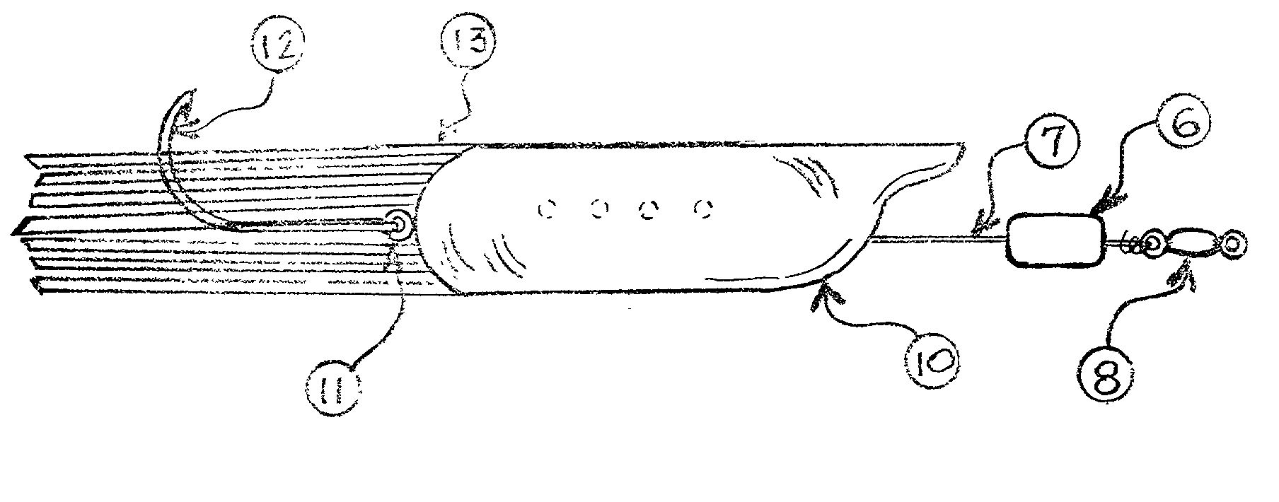
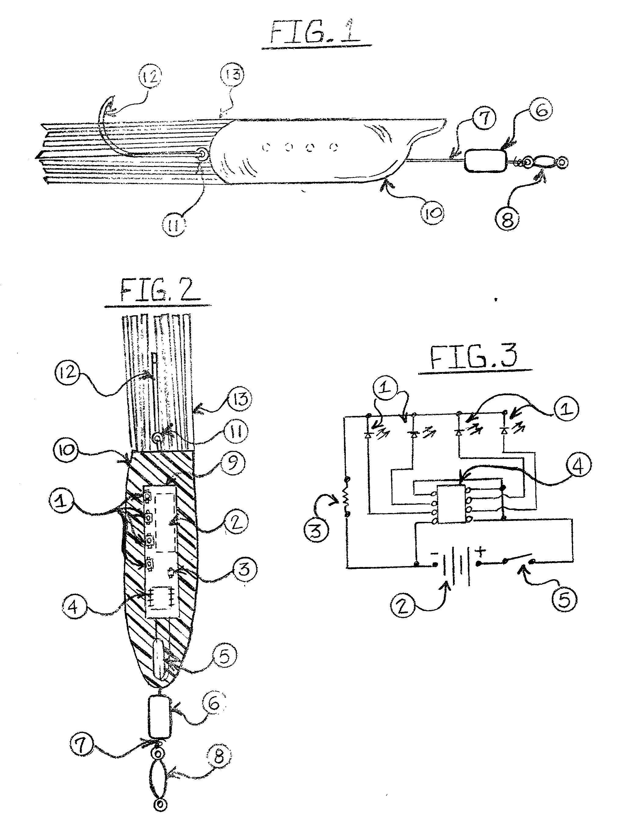
[0026] Referring to the figures, in particular FIG. 1 and FIG. 2, the fishing lure which is shown generally is comprised of body 10, generally made of a resin-like translucent material, thus assisting in the illumination of the entire body by the LED's 1. Body 10 is provided with a hook 12 secured to the body 10 by means of an eyelet 11. Additionally attached to the body 10 is leader material 7, a magnet 6, metallic barrel swivel 8 allowing for attachment to fishing line, and tail material 13.

[0027] FIG. 2 shows generally the various components housed inside the body 10. It will be understood that FIG. 2 is used by way of illustration only and is not intended to accurately depict electrical connections of the various components that go to make up the power source or used to energize the LED's 1.

[0028] When the lure is at rest, magnet 6 is magnetically held away from the reed switch 5 by a metallic barrel swivel 8. To activate, slide magnet 6 towards body 10. This will activate the r...


PUM


Abstract

A fishing lure utilizing a solid, resin-like body encapsulating electrical circuits, including an internal oscillating microchip, in a translucent bait shaped body. Several light emitting diodes are programmed to blink sequentially in a predetermined pattern, thus illuminating the entire lure body. An externally attached magnet is moved toward an internal reed switch to activate the LED's. The lure is disposable with no requirements for changing encapsulated battery.

Description

BACKGROUND--FIELD OF INVENTION[0001] This invention relates to illuminated fishing lures. This lure utilizes light emitting diodes (LED's) programmed to flash in a specific sequence. The LED's are encapsulated in the body, allowing the entire body to illuminate, thus increasing the effectiveness of the lure.BACKGROUND--DESCRIPTION OF PRIOR ART[0002] Prior art devises are typically clumsy, requiring disassembly to remove the battery in order to turn on and shut off the light source. They can also be dangerous to the operator by requiring the jarring of the device for the battery to make contact with the light source, or by having to take the lure apart and changing or inserting batteries. These devices contain hooks and can be hazardous to handle.[0003] The current devices utilizing LED's as illumination have limited visibility. The LED's are usually placed at the position of the eyes of the device. This makes only a small portion of the device visible when the LED's are activated.[0...

Claims


Application Information

Patent Timeline
IPC IPC(8): A01K85/01
CPCA01K85/01
Inventor CALAK, CHARLES THOMAS JR.DEL CASINO, GLORIA
Owner CALAK CHARLES THOMAS JR
Why Eureka
Try Eureka