
Pivoting rod holder

a technology of fishing rods and holders, which is applied in the direction of stand/trestle, other angling devices, kitchen equipment, etc., can solve the problems of not being able to meet the needs of marine vessels, occupy a large amount of space, and many rod holders currently availabl

Inactive Publication Date: 2003-10-02
LOBOSTAR
View PDF0 Cites 12 Cited by
  • Summary
  • Abstract
  • Description
  • Claims
  • Application Information

AI Technical Summary

Benefits of technology

[0239] After reviewing the above information, the reader will be able to see that the pivoting rod holder discussed here provides a vast improvement over the extensive variety of rod holders and rod holding systems that already exist in this field. It is simple in design and easy to manufacture. It is compact, low in weight, and mounts easily to the gunwales of marine-going vessels. It adjusts 360 degrees in any direction, and can be locked in any one of those directions by simply pulling back on the rod holder tube. Releasing it from a secured position involves simply pushing the rod holder tube back into a straight up and down position where it is parallel with the base. In addition to these advantages, other advantages of this pivoting rod holder are:
[0240] It is not bulky and as a result can be mounted easily to a variety of gunwales. Many of the rod holders currently available are bulky and take up a large amount of room. This is not acceptable on marine vessels where space is already in short supply. Also, the larger the rod holder the greater the chance of someone accidentally bumping into it and getting injured. The small size and compactness of the pivoting rod holder, and the fact that it stows away in the gunwale, minimizes the possibility of injury and saves valuable space.
[0241] It is very adjustable. The rod holder tube can be rotated a full 360 degrees and can be snap-locked at an angle into any position along the 360 degree axis. If another position is desired, the rod holder tube is easily disengaged by pushing or pulling it back into a straight up and down position, spun to the desired direction along the 360 degree axis, and snapped into that new position
[0242] It is easy to operate. To set it in a desired position, all that needs to be done is pull the rod holder tube up all the way, rotate it to the desired position, and then pull or push it until it snap-locks into one of the catch indentations in the rod holder base. To release it, all that is needed is to push or pull it away from the catch indentation until the plunger pops out, straighten the rod holder tube into the vertical position, and either re-stow it or rotate and snap it into another position.
[0243] It allows striking of fish without having to remove the fishing rod from the rod holder. Striking a fish involves pulling sharply back on the fishing rod once a fish has taken the bait and engaged the hook. It allows the fisherman to pull the fish aboard the vessel quickly before the fish has a chance to get away. To strike a fish while using a fixed rod holder that cannot be pulled back quickly or pulled back at all, the fisherman has to remove the rod from the rod holder before striking the fish. This wastes time and often results in the fisherman losing the fish while going to the trouble to remove the rod from the rod holder. With the pivoting rod holder, the rod holder tube can be pulled back quickly and locked into a fixed position with the rod still in it. This means the fisherman can strike the fish without having to remove the rod from the rod holder tube. This results in greater convenience and fewer lost catches.
[0244] Since it is made of anodized and waterproofed materials, it will not rust or corrode. The materials that make the pivoting rod holder light are also resistant to corrosion and rust caused by saltwater and / or humidity. This ensures that the pivoting rod holder has a long, durable life of use.

Problems solved by technology

Many of the rod holders currently available are bulky and take up a large amount of room.
This is not acceptable on marine vessels where space is already in short supply.
Also, the larger the rod holder the greater the chance of someone accidentally bumping into it and getting injured.

Method used


Image

  • Pivoting rod holder
  • Pivoting rod holder
  • Pivoting rod holder

Examples


Embodiment Construction

Of Invention--FIGS. 1-10, FIG. 15D, FIG. 15E

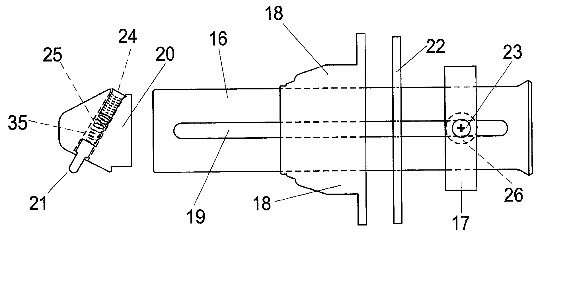
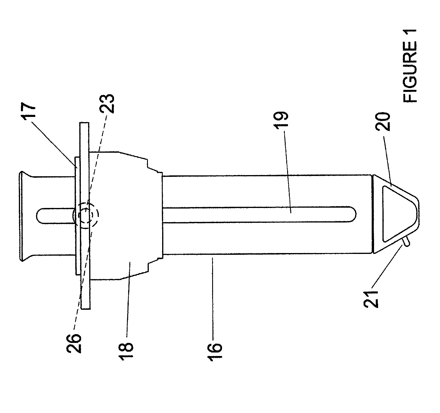
[0218] Referring in greater detail to the drawings, FIG. 1 is a side view that shows the pivoting rod holder in its retracted or stowed state. The rod holder tube slot(s) 19 and rod holder tube 16 are anchored to collar 17 by screw(s) 23 and nylon washer(s) 26. Collar 17 with rod holder tube 16 resides in base 18. It is the rod holder tube slot(s) 19 that allow the rod holder tube 16 to move up and down through base 18. At the end of rod holder tube 16 is bottom cap 20 Protruding from bottom cap 20 is plunger 21.

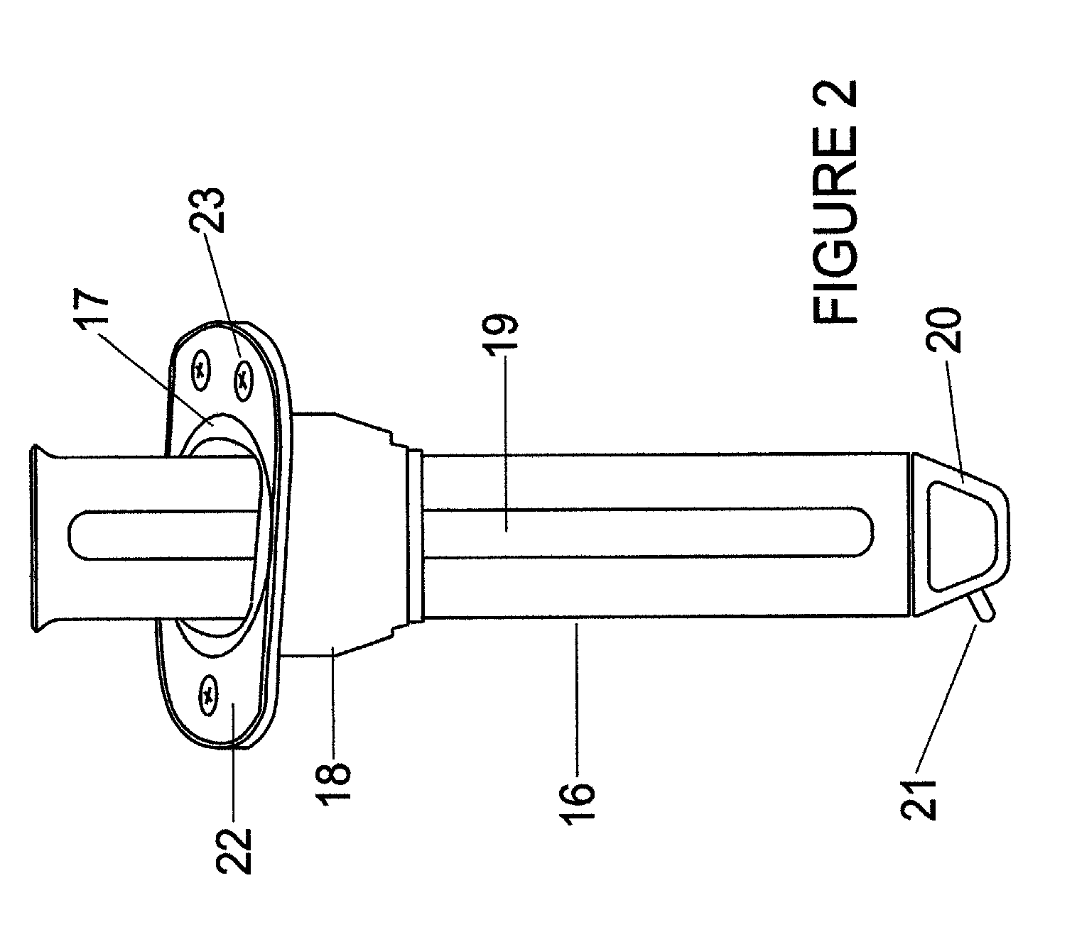
[0219] FIG. 2 is another side view but with an additional perspective of looking down at the invention. Bottom cap 20 with plunger 21 occupies end of rod holder tube 16. Along length of rod holder tube 16 is rod holder tube slot(s) 19. Rod holder tube 16 occupies base 18, which encloses collar 17 and retaining plate 22. It is through retaining plate 22 that screw(s) 23 are inserted to secure base 18 to the gunwale of a ship.

[0220] ...


PUM


Abstract

A Pivoting Rod Holder for securing fishing rods in a variety of positions while they are in use is described. A rod holder tube is a component of a pivoting rod holding system, which has as its additional components a base with a plurality of catch indentations, a collar, a retaining plate, and a plunger-operated locking mechanism at the base of the rod holder tube. A rod placed in the rod holder tube can be locked into any position along a 360 degree axis by simply pulling the rod holder tube up till it is parallel with the catch indentations in the base, spinning it into the desired position, and pulling back firmly on it. This pushes the plunger-operated locking mechanism at the base of the rod holder tube into one of the catch indentations in the base, where it is secured. To release, the rod holder tube is pushed on until the plunger-operated locking mechanism is popped out of the catch indentation in the base. It can then be reset using the same process as above or can be re-stowed by returning it to the vertical position and pushing down.

Description

[0001] 1. Field of Invention[0002] This invention relates to pivoting fishing rod holders, specifically those for use aboard recreational marine vessels.[0003] 2. Description of Prior Art[0004] Aboard recreational marine craft where people engage in fishing activity that requires the use of fishing rods, it is impossible for the people who are fishing to hang on to their fishing rods during the entire trip at sea. Some type of device or implement is needed, therefore, to secure the rod or rods while people aboard the boat attend to other tasks. It is because of this need that a staggering variety of fishing rod holders have been invented and are currently on the market. In fact, there are many, if not hundreds, of varieties of fishing rod holders currently available or in the process of development. Most of these rod holders fall into three kinds of categories; the non-adjustable type for simply storing the rods while they are not in use, the non-adjustable type for holding the rods...

Claims


Application Information

Patent Timeline
Patent Type & Authority Applications(United States)
IPC IPC(8): A01K97/10
CPCA01K97/10
Inventor RUIZ, EDWINRUIZ, HANS
Owner LOBOSTAR
Learn More