Apparatus for and method of measurement of aspheric surfaces using hologram and concave surface

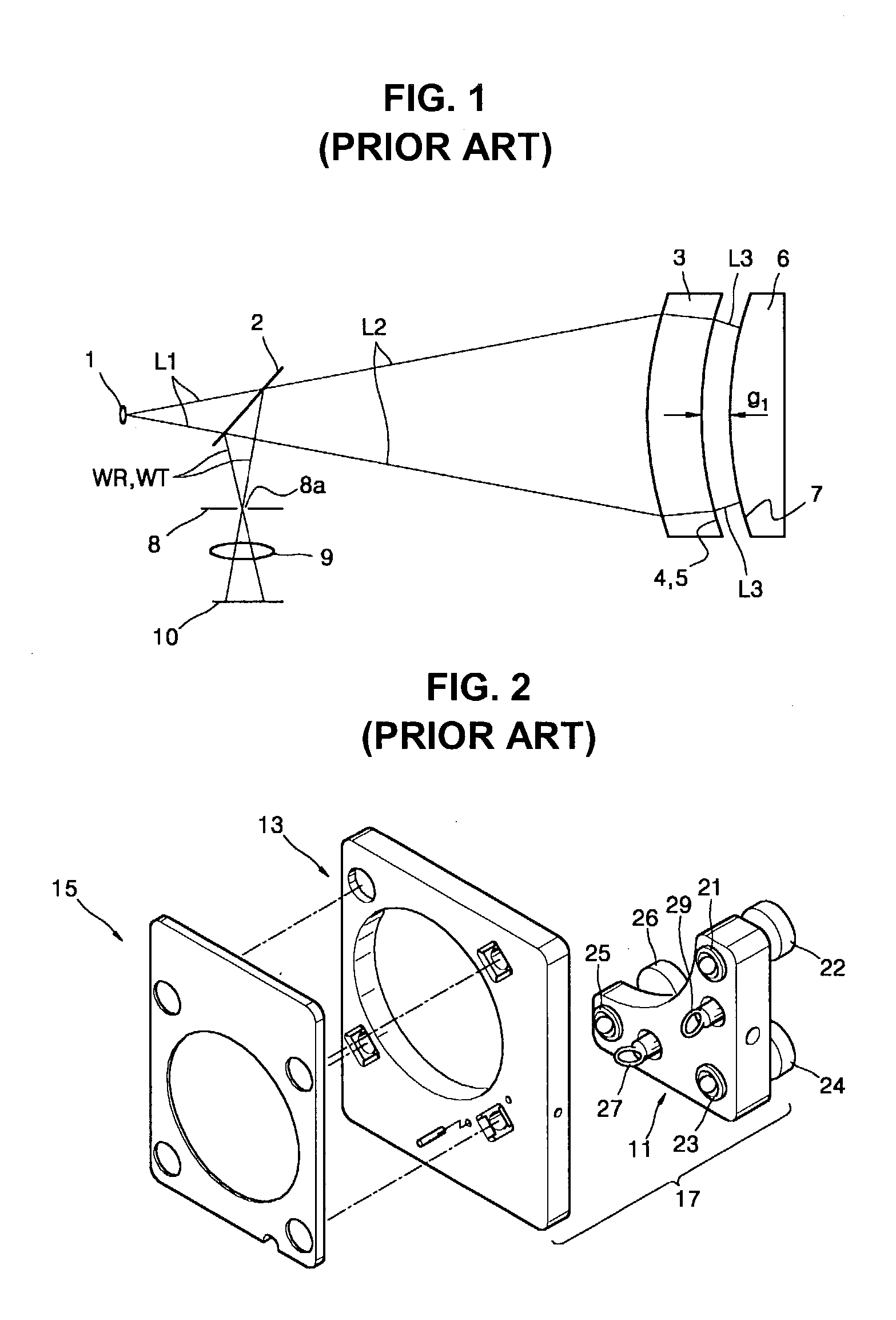
a technology of aspheric surfaces and apparatuses, applied in the direction of geometric properties/aberration measurement, structural/machine measurement, instruments, etc., can solve the problems of mechanical adjustment errors, measurement errors, and difficulty in manufacturing test plate members 3 with such a high degree of surface precision

Inactive Publication Date: 2003-10-02
SAMSUNG ELECTRONICS CO LTD
View PDF8 Cites 33 Cited by
  • Summary
  • Abstract
  • Description
  • Claims
  • Application Information

AI Technical Summary

Benefits of technology

0018] In one aspect, the present invention provides an apparatus for measuring aspheric surfaces, comprising an interferometer which generates incident light, a test piece having an aspheric surface from which the incident light is reflected as test light, a first optical element disposed on an optical path of the incident light and having at least one surf

Problems solved by technology

However, it is difficult to manufacture the test plate member 3 with such a high degree of surface precision.
When the optical paths of the reference light WR and the test light WT are not common in such an aspheric surface measuring apparatus, measurement errors occur due to environmental factors, such as external vibration.
In the aspheric surface testing apparatus of FIG. 2, since the base 11

Method used


Image

  • Apparatus for and method of measurement of aspheric surfaces using hologram and concave surface
  • Apparatus for and method of measurement of aspheric surfaces using hologram and concave surface
  • Apparatus for and method of measurement of aspheric surfaces using hologram and concave surface

Examples


Embodiment Construction

[0050] Embodiments of the invention will be described in detail with reference to the accompanying drawings, wherein like reference numerals refer to the like elements throughout. The embodiments are described below in order to explain the present invention by referring to the figures. In the drawings, the size and thickness of elements are exaggerated for clarity.

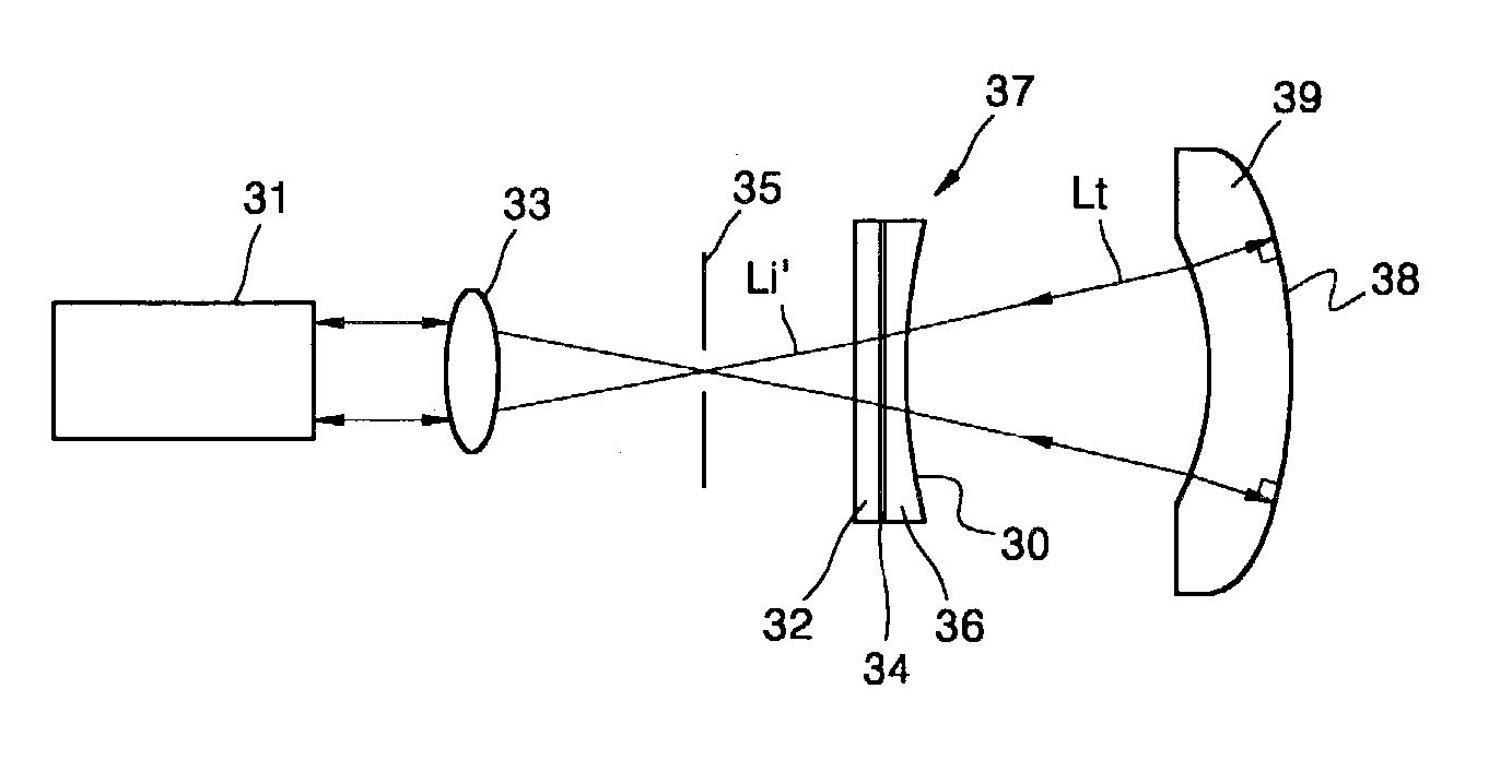
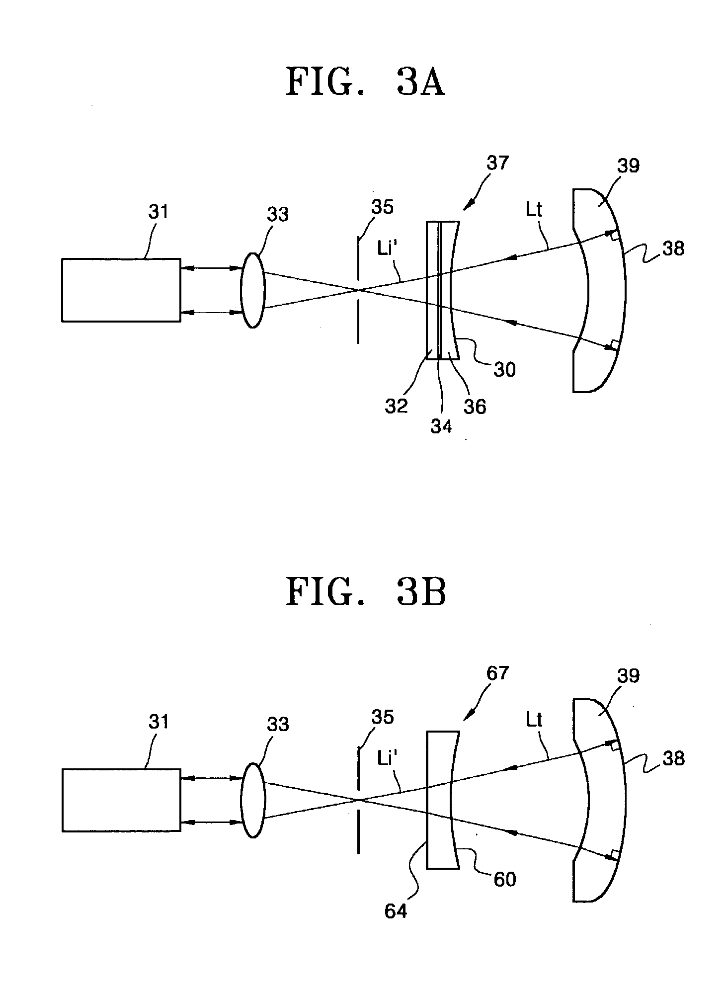
[0051] FIGS. 3A and 3B show embodiments of the apparatus for measuring aspheric surfaces according to the present invention. Referring to FIG. 3A, the aspheric surface measuring apparatus includes an interferometer 31, a condensing lens 33 which condenses light emitted from the interferometer 31, and a spatial filter 35 which spatially modulates the frequency of the condensed light. A first optical member 37 having a hologram 34 and a concave surface 30 diffracts and diverges, respectively, incident light Li' from the spatial filter 35. A test piece 39 having an aspheric surface 38 to be measured receives light from the fi...


PUM


Abstract

An aspheric surface measuring apparatus includes an interferometer which generates incident light; a test piece having an aspheric surface from which the incident light is reflected as test light; a first optical element disposed on an optical path of the incident light, having at least one surface with a hologram for diffracting the incident light toward the test piece; and a second optical element disposed after the first optical element, which transmits the incident light toward the aspheric surface and has a concave surface to reduce an incident angle of the test light entering the hologram after having been reflected from the aspheric surface. Alternatively, a single optical element with a hologram and a concave surface can be used instead of the separate first and second optical elements. An extremely aspheric lens can be precisely measured using the apparatus.

Description

[0001] This application claims the benefit of Korean Application No. 2001-82483 filed Dec. 21, 2001 in the Korean Intellectual Property Office, the disclosure of which is incorporated herein by reference.[0002] 1. Field of the Invention[0003] The present invention relates to an apparatus and method of measuring aspheric surfaces, and more particularly, to an apparatus and method of measuring aspheric surfaces using a hologram.[0004] 2. Description of the Related Art[0005] Aspheric lenses are widely used in a variety of products, including large-scale projection display systems and camcorders. The trend toward light-weight, small, and high-picture quality apparatuses has gradually increased the diameter and asphericity of the aspheric lens. The manufacture of the aspheric lens needs high precision and accuracy in shaping the aspheric lens. Accordingly, an apparatus and method to measure the shape of the aspheric lens with high precision using a hologram and interferometer have been d...

Claims


Application Information

Patent Timeline
IPC IPC(8): G01B9/02G01B9/021G01B11/24G01M11/00G01M11/02
CPCG01B9/021G01M11/0271G01M11/025G01B9/02
Inventor KIM, TAE-HEEBURGE, JAMES H.
Owner SAMSUNG ELECTRONICS CO LTD
Why Eureka
Try Eureka