Bottom fluorescence illumination assembly for an imaging apparatus

a technology of illumination assembly and imaging apparatus, which is applied in the direction of fluorescence/phosphorescence, optical radiation measurement, spectrometry/spectrometry/monochromator, etc., can solve the problems of requiring specialized cooling, presenting particular design challenges, and requiring specialized cooling, so as to reduce the autofluorescence background signal of the specimen

Inactive Publication Date: 2003-10-02
XENOGEN CORP
View PDF9 Cites 24 Cited by
  • Summary
  • Abstract
  • Description
  • Claims
  • Application Information

AI Technical Summary

Benefits of technology

[0011] Accordingly, by illuminating the specimen through a bottom side illumination thereof with an excitation light source, as opposed to a topside illumination of the specimen, the autofluorescence background signal of the specimen itself is reduced. This is due to the fact that tissue autofluorescense is always higher on the side of the excitation light source than on the side facing the camera. In the case of a topside illumination, both the camera and the excitation light source are on the same side.

Problems solved by technology

Such imaging applications present particular challenges to the design of a box or chamber in which the sample is contained during imaging.
These cameras are generally complex, may require specialized cooling, and are typically fixed to a single location on the top of a specimen chamber.
Due to this static design, one particular challenge to imaging apparatus design is the diverse lighting needs required during image capture.
One problem associated with the capture of overhead images in macroscopic applications is that the relatively large CCD camera is typically centrally located directly over the sample platform which supports the sample.
Thus, for relatively non-planar samples supported atop the platform, substantially uniform illumination is difficult to achieve.
Such is also the case when multiple illumination sources are applied which often causes detrimental shadowing, and thus, non-uniform lighting.
Another problem associated with fluorescent imaging in macroscopic applications is that the current imaging apparatus generally employ dichroic mirrors to perform partial filtering functions.
This of course necessitates the use of a much larger lens which in turn renders the use of a dichroic mirror impractical.
Due to the size and orientation of such a mirror in the imaging compartment of the imaging box, the footprint of the imaging box is unfeasibly large.

Method used


Image

  • Bottom fluorescence illumination assembly for an imaging apparatus
  • Bottom fluorescence illumination assembly for an imaging apparatus
  • Bottom fluorescence illumination assembly for an imaging apparatus

Examples


Embodiment Construction

[0040] While the present invention will be described with reference to a few specific embodiments, the description is illustrative of the invention and is not to be construed as limiting the invention. Various modifications to the present invention can be made to the preferred embodiments by those skilled in the art without departing from the true spirit and scope of the invention as defined by the appended claims. It will be noted here that for a better understanding, like components are designated by like reference numerals throughout the various figures.

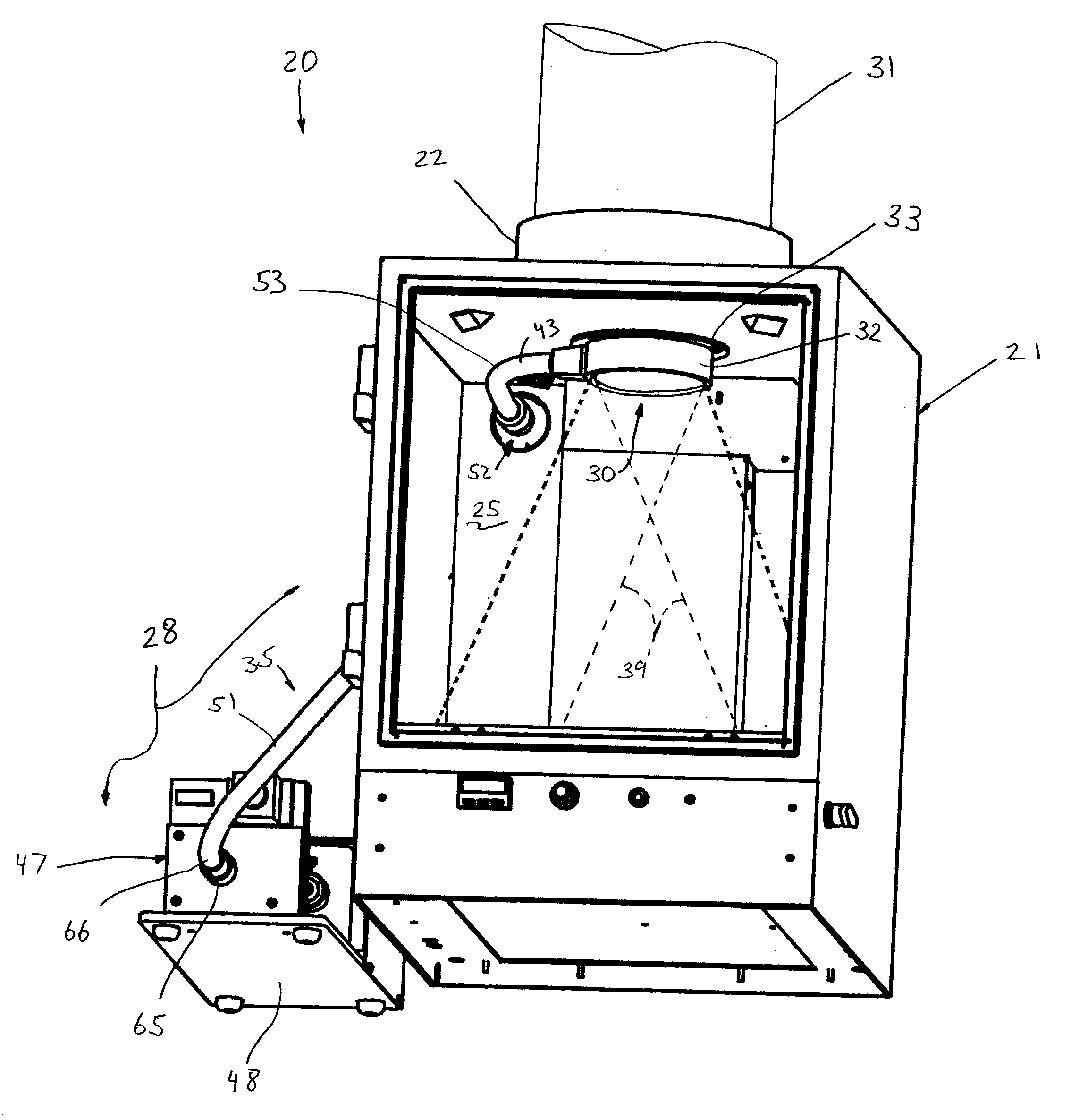
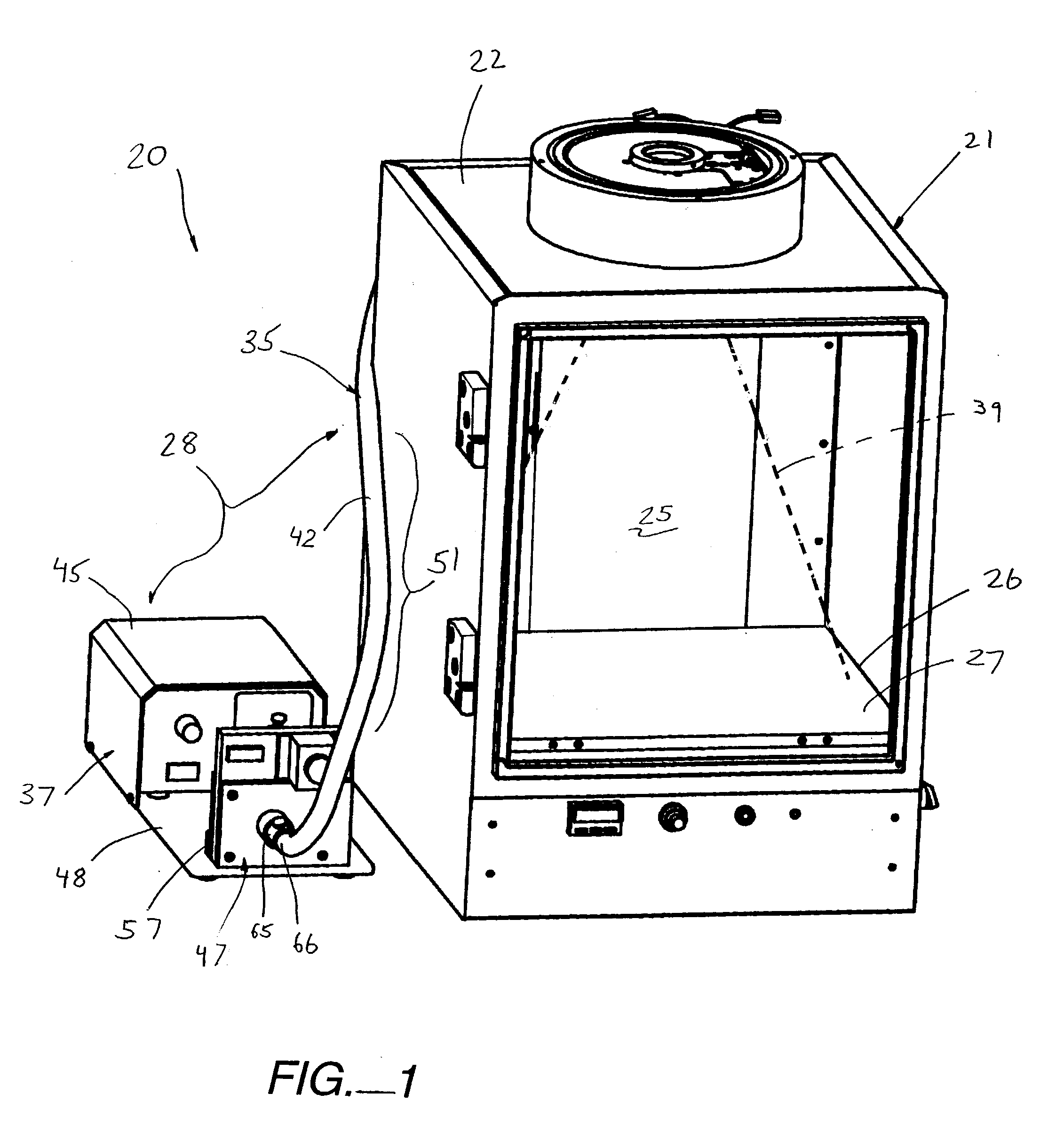
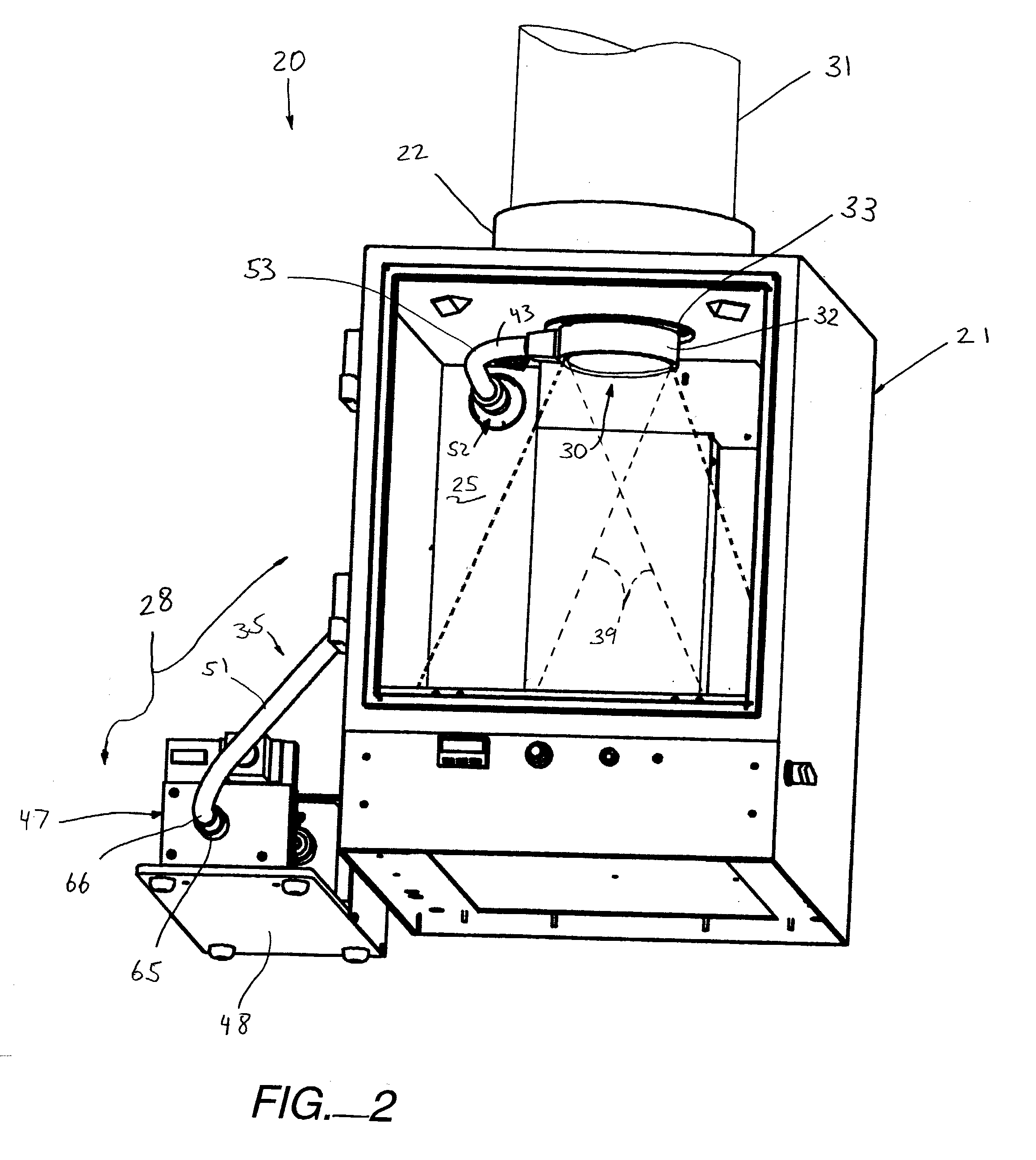
[0041] Referring now to FIGS. 1-5, a fluorescence imaging assembly, generally designated 20, is provided which includes a light-tight sample box or imaging apparatus 21 having an enclosure wall or upper housing 22 defining a view port 23 (FIG. 5) into a light-tight imaging compartment 25 thereof. A specimen platform 26 is positioned in the imaging compartment 25 which includes a support surface 27 facing toward the view port 23. T...


PUM

PropertyMeasurementUnit
angleaaaaaaaaaa
diameteraaaaaaaaaa
angleaaaaaaaaaa

Abstract

A macroscopic fluorescence illumination assembly is provided for use with an imaging apparatus with a light-tight imaging compartment. The imaging apparatus includes an interior wall defining a view port extending into the imaging compartment to enable viewing of a specimen contained therein. The illumination assembly includes a specimen support surface sized and dimensioned for receipt in the imaging compartment, and oriented to face toward the view port of the imaging apparatus. The support surface is substantially opaque and defines a window portion that enables the passage of light there through. The window portion is selectively sized and dimensioned such that the specimen, when supported atop the support surface, can be positioned and seated over the window portion in a manner forming a light-tight seal substantially there between. The illumination assembly further includes an excitation light source, and a bundle of fiber optic strands having proximal ends thereof in optical communication with the light source. The distal ends of the strands terminate proximate the window portion of the support surface. The distal ends each emit a respective beam of light originating from the light source which are then collectively directed toward the window portion and into a bottom side of the specimen wherein the diffused light passes there through and exits a topside thereof for receipt through the view port to view the fluorescence of the specimen.

Description

[0001] This application is a continuation-in-part of a U.S. patent application entitled "FLUORESCENCE ILLUMINATION ASSEMBLY FOR AN IMAGING APPARATUS" by Nilson et al., filed Jul. 3, 2002, U.S. application Ser. No. 10 / 081,040, which in turn claims priority under 35 U.S.C. 119(e) from U.S. Provisional Patent Application No. 60 / 359,663, entitled same and filed Feb. 22, 2002, both of which are incorporated herein by reference for all purposes.[0002] The present invention relates generally to imaging systems, and more particularly, relates to macroscopic, bottom fluorescent illumination sources and their associated components to illuminate imaging systems.[0003] One specialized type of imaging involves the capture of low intensity fluorescence. Briefly, fluorescence is a molecular phenomenon in which a substance absorbs light of a particular wavelength and emits light of a longer wavelength. The absorption of light is referred to as the "excitation", and the emission of longer wave light...

Claims


Application Information

Patent Timeline
Patent Type & Authority Applications(United States)
IPC IPC(8): A01K1/03A22B3/00A61M16/00A61M16/10A61M16/18A61M16/20G01N21/64
CPCA01K1/031A61M16/104A61M16/18A61M2016/0039G01N21/6456A61M16/202G01N2021/6463G01N2021/6471G01N2021/6484G01N2201/0227G01N2201/0826G01N2021/1787
Inventor NILSON, DAVIDRICE, BRADTROY, TAMARA
Owner XENOGEN CORP
Why Eureka
Try Eureka