Versatile cavity actuator and systems incorporating same

a technology of actuators and cavities, applied in the field of energetic cavities, can solve the problems of incompatibility of temperature-sensitive applications, such as integrated circuit applications, with accurate and expensive manufacturing processes, and increase actuator costs and dud rates

Inactive Publication Date: 2003-10-16
TANNER RES
View PDF7 Cites 19 Cited by
  • Summary
  • Abstract
  • Description
  • Claims
  • Application Information

AI Technical Summary

Problems solved by technology

Accurate and expensive manufacturing processes are often required to ensure precise positioning of the charge relative to the heater.
These stringent positioning requirements may increase actuator costs and dud rates.
Consequently, temperature-sensitive applications, such as integrated circuit applications, are often incompatible with the microcavity actuators.
Furthermore, these microcavity actuators often require a rigid silicon substrate, which severely limits actuator versatility and applicability.
In addition, requisite construction materials and microcavity processing steps often necessitate vertical cavity sidewalls.
Vertical cavity sidewalls may yield undesirable blast characteristics for some applications.
However, device design constraints necessitate a rigid silicon substrate, which may require either expensive reactive ion etching or high-temperature manufacturing steps that are incompatible with many applications.
Furthermore, these cavities typically require an electrical path through the substrate, which is problematic, especially in applications requiring special substrates, such as Integrated Circuit (IC) applications.

Method used


Image

  • Versatile cavity actuator and systems incorporating same
  • Versatile cavity actuator and systems incorporating same
  • Versatile cavity actuator and systems incorporating same

Examples


first embodiment

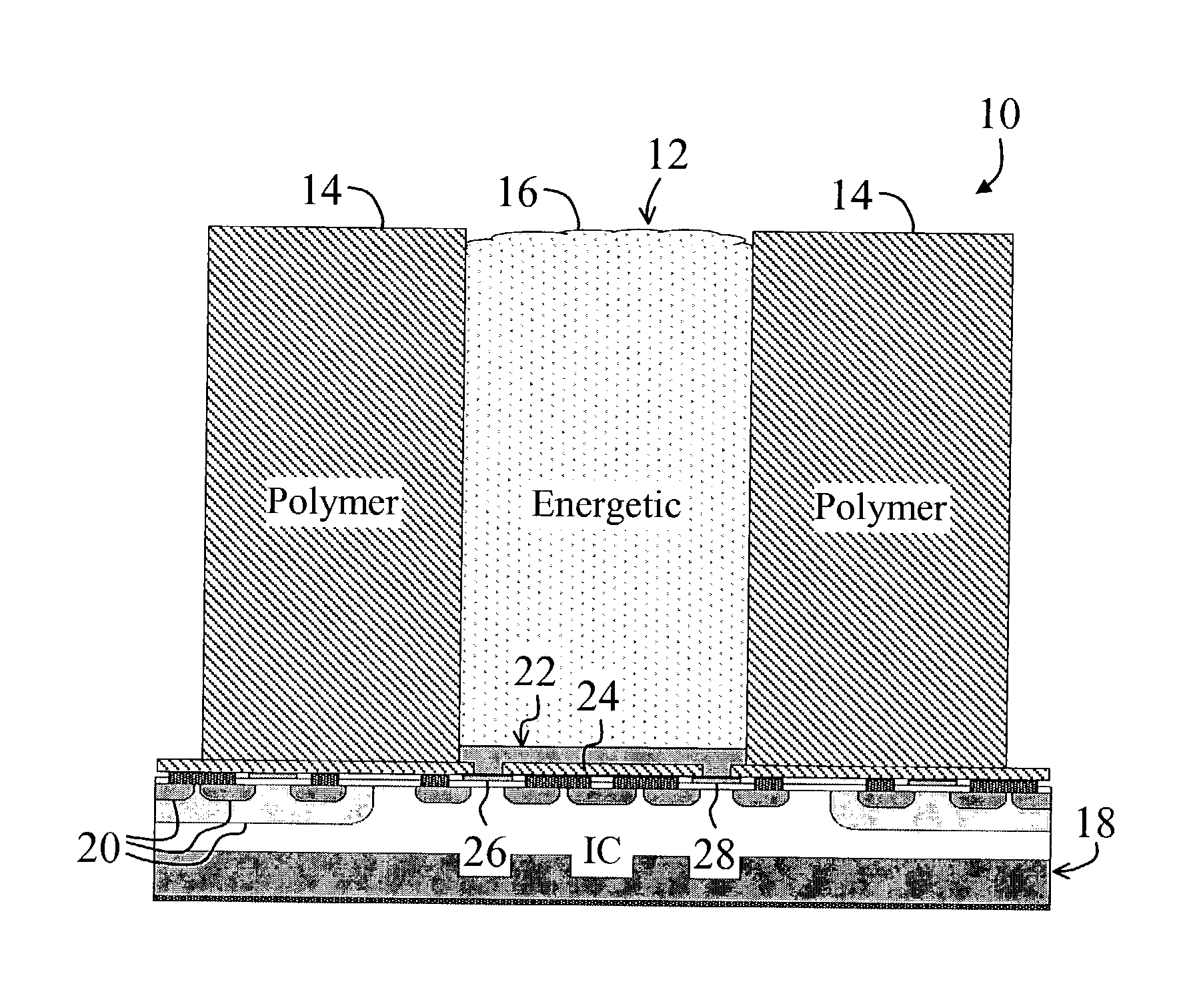
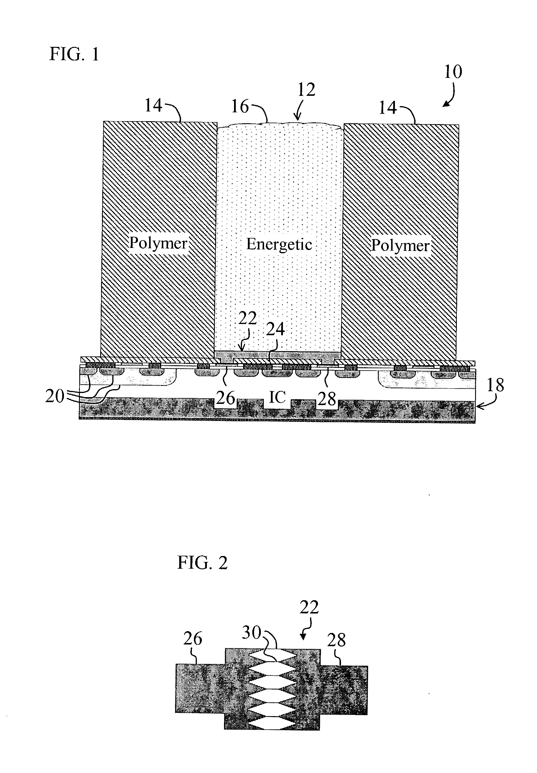
[0024] FIG. 1 is a diagram of a microcavity actuator 10 constructed in accordance with the teachings of the present invention and mounted on an Integrated Circuit (IC) 18. For clarity, various well-known components, such as power supplies, contact pads, and so on, have been omitted from the figures, however those skilled in the art with access to the present teachings will know which components to implement and how to implement them to meet the needs of a given application.

[0025] For the purposes of the present discussion, a microcavity actuator is any miniature cavity actuator, such as an initiator or thruster. For example, cavity initiators with dimensions on the order of nanometers or millimeters are also microcavity actuators. Cavity actuators are often called Electro-Explosive Devices (EED's).

[0026] The microcavity actuator 10 includes a cavity 12 having electrically and thermally insulating polymer sidewalls 14 and energetic material 16, such as explosives, disposed therein. F...

second embodiment

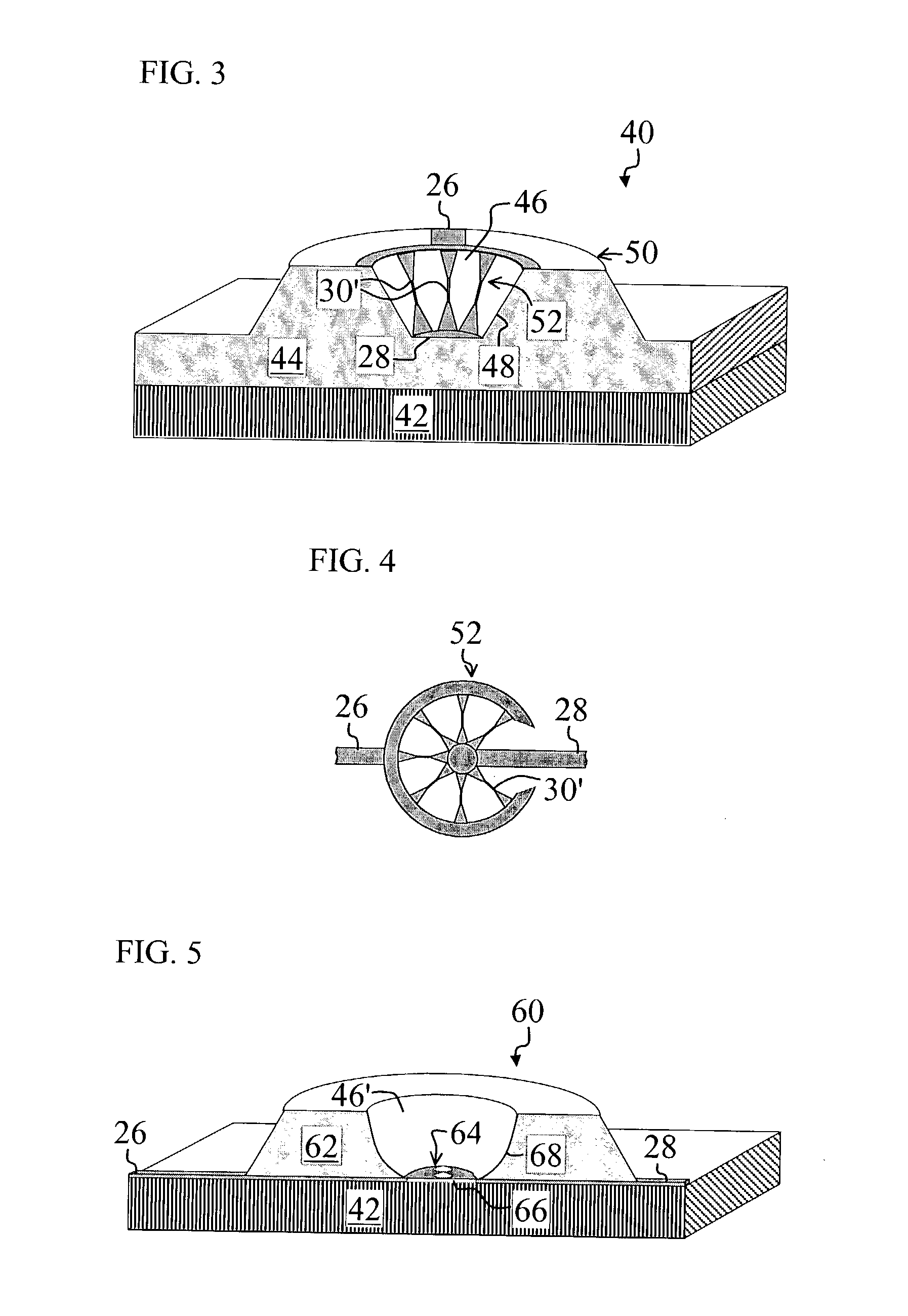
[0042] FIG. 3 is a diagram of a microcavity actuator 40 employing a unique side-wall heater 52 and having angled polymer sidewalls 48 constructed in accordance with the teachings of the present invention. The microcavity actuator 40 is formed on a substrate 42, such as glass, conformal plastic, a temperature-sensitive IC, or other substrate. The microcavity actuator 40 is formed in a polymer 44 that is disposed on the substrate. A partially conical cavity 46 has angled sidewalls 48 that are supported by a raised portion 50 of the polymer 44. Other cavity shapes, such as rectangular or square cavities with one or more angled sidewalls, may be employed without departing from the scope of the present invention.

[0043] The cavity 46 is equipped with the unique angled sidewall heater 52, which includes multiple angled bow-tie sections 30'. The angled bow-tie sections 30' are disposed along the angled cavity walls 48. The anode 26 connects to top ends of the angled bow-tie sections 30' alo...


PUM


Abstract

A versatile cavity actuator. The versatile cavity actuator includes a cavity having one or more polymer-based sidewalls. An energetic material is disposed therein. A heater is disposed on or within the cavity. In a specific embodiment, the cavity includes a thermally insulating base positioned beneath the heater, which is positioned near the bottom of the cavity. The polymer-based sidewalls are constructed from a photo-curable epoxy, which is disposed on a substrate via microelectromechanical processes. The sidewalls are angled or parabolic and are constructed via a low-temperature lithographic spin process compatible with post integrated circuit processing.

Description

CLAIM OF PRIORITY[0001] This application claims priority from U.S. Provisional Patent Application Serial No. 60 / 372,251, filed Apr. 11, 2002, entitled INTEGRATED POLYMER MICRO CAVITIES WITH INITIATORS FOR ENERGETIC APPLICATIONS, which is incorporated by reference herein.[0002] 1. Field of Invention[0003] This invention relates to energetic cavities. Specifically, the present invention relates to miniature cavities equipped with energetic material.[0004] 2. Description of the Related Art[0005] Miniature cavities, such as explosives-filled microcavities and nanocavities, are employed in various demanding applications including micro thrusters, safe-and-arm devices, and airbag initiators. Such applications require versatile, highly controllable, and cost-effective cavities with specific blast characteristics.[0006] Some existing microcavity actuators include explosives-filled cavities etched in silicon. A polysilicon bridge wire detonator is often positioned on top of the explosives-fi...

Claims


Application Information

Patent Timeline
Patent Type & Authority Applications(United States)
IPC IPC(8): B64G1/26B64G1/40F02K9/94F42B3/00
CPCB64G1/26B64G1/403F42B10/661F42B3/006F02K9/94
Inventor DESAI, AMISHVERMA, RAVI KANTSIVILOTTI, MASSIMO ANTONIO
Owner TANNER RES
Why Eureka
Try Eureka