Analytical constraint generation for cut-based global placement

a global placement and constraint technology, applied in the field of fabrication and design of semiconductor chips and integrated circuits, can solve the problems of large number of cells, difficult computer-aided design, and complicated connections between cells,

Inactive Publication Date: 2003-10-16
GLOBALFOUNDRIES US INC
View PDF0 Cites 16 Cited by
  • Summary
  • Abstract
  • Description
  • Claims
  • Application Information

AI Technical Summary

Problems solved by technology

An IC may include a very large number of cells and require complicated connections between the cells.
Due to the large number of components and the details required by the fabrication process, physical design is not practical without the aid of computers.
Consequently, placement now resembles the problem of arranging "dust" logic around these large blocks.
However, even though the dust logic is a small percentage of the chip area, there can still be millions of cells in the dust logic that have profound effects on timing and routability.
Such recursive cut-based placement can perform quite

Method used


Image

  • Analytical constraint generation for cut-based global placement
  • Analytical constraint generation for cut-based global placement
  • Analytical constraint generation for cut-based global placement

Examples


Embodiment Construction

)

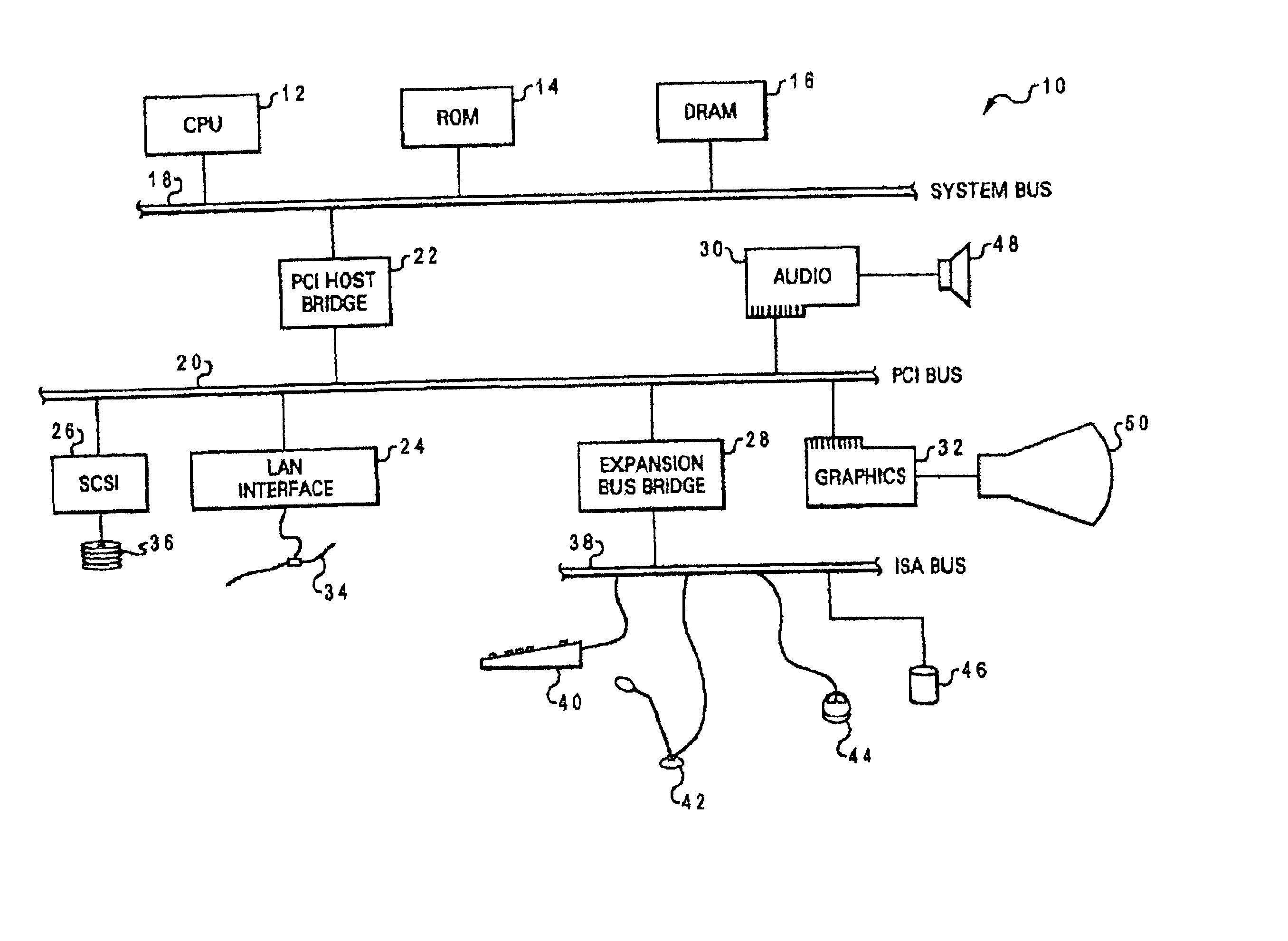
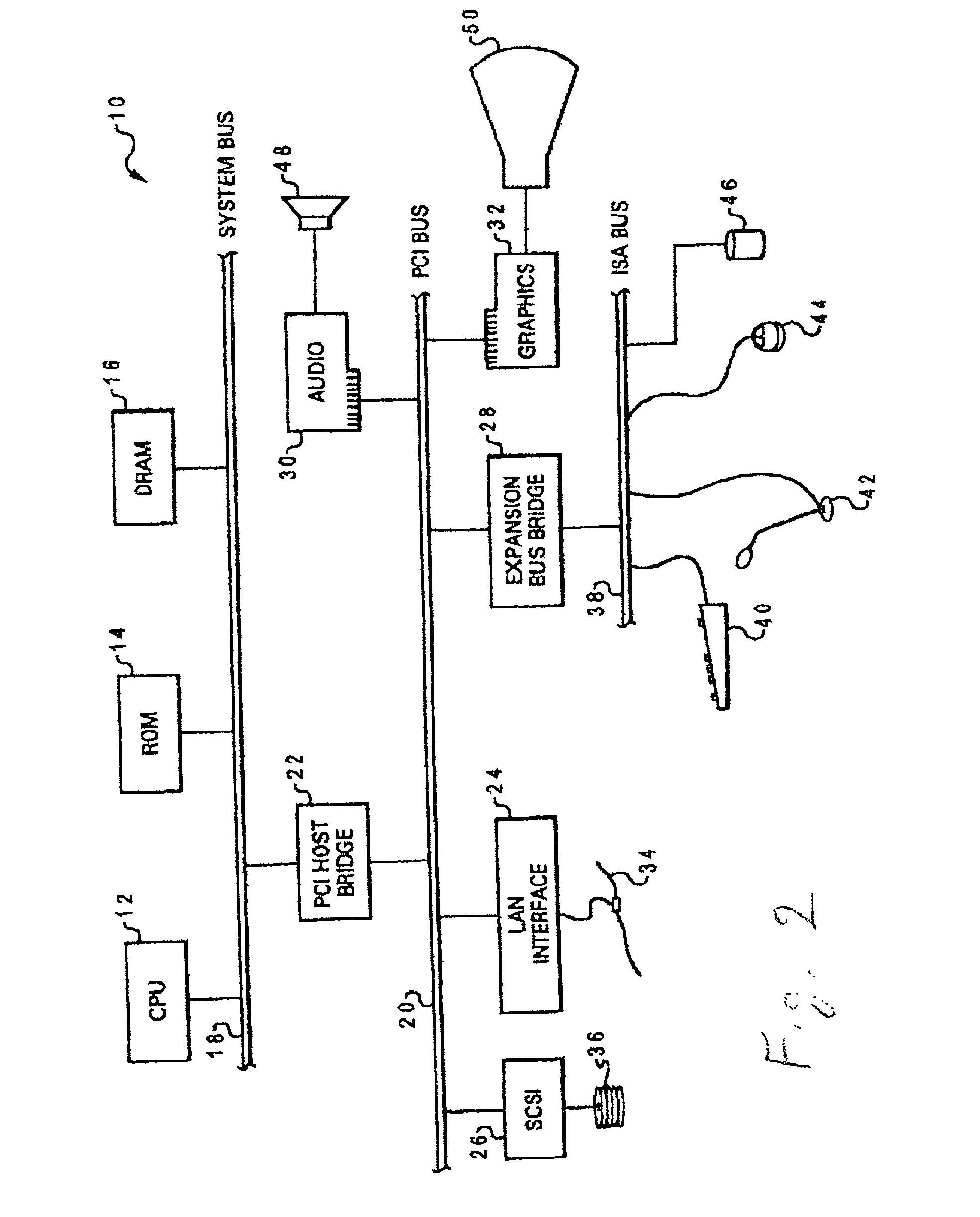
[0029] With reference now to the figures, and in particular with reference to FIG. 2, there is depicted one embodiment 10 of a computer system programmed to carry out computer-aided design of an integrated circuit in accordance with one implementation of the present invention. System 10 includes a central processing unit (CPU) 12 which carries out program instructions, firmware or read-only memory (ROM) 14 which stores the system's basic input / output logic, and a dynamic random access memory (DRAM) 16 which temporarily stores program instructions and operand data used by CPU 12. CPU 12, ROM 14 and DRAM 16 are all connected to a system bus 18. There may be additional structures in the memory hierarchy which are not depicted, such as on-board (L1) and second-level (L2) caches.

[0030] CPU 12, ROM 14 and DRAM 16 are also coupled to a peripheral component interconnect (PCI) local bus 20 using a PCI host bridge 22. PCI host bridge 22 provides a low latency path through which processor 12 ...


PUM


Abstract

A method of designing the layout of an integrated circuit (IC) by deriving an analytical constraint for a cut-based placement partitioner using analytical optimization, and placing cells on the IC with the cut-based placement partitioner using the analytical constraint. Quadratic optimization may be used to determine a desired ratio of a cell area of a given partition to a total cell area (the balance parameter), and placing may be performed using multilevel bisection partitioning constrained by the balance parameter. This implementation may include a determination of an aspect ratio for an entire partitioning region of the integrated circuit, and a "center-of-mass" coordinate of the cells based on the quadratic optimization, which are then used to define a placement rectangle having the same aspect ratio, and centered on the center-of-mass coordinate. This placement rectangle is used to derive the balance parameter. The placement rectangle has a total area equal to a total moveable cell area, and the balance parameter is computed by calculating the ratio of a left portion of the placement rectangle which lies in the left partition to the total area of the placement rectangle. The multilevel partitioner then places a proportionate number of the cells in the left partition based on the balance parameter.

Description

[0001] 1. Field of the Invention[0002] The present invention generally relates to the fabrication and design of semiconductor chips and integrated circuits, and more particularly to a method of designing the physical layout (placement) of logic cells in an integrated circuit, and the wiring (routing) of those cells.[0003] 2. Description of the Related Art[0004] Integrated circuits are used for a wide variety of electronic applications, from simple devices such as wristwatches, to the most complex computer systems. A microelectronic integrated circuit (IC) chip can generally be thought of as a collection of logic cells with electrical interconnections between the cells, formed on a semiconductor substrate (e.g., silicon). An IC may include a very large number of cells and require complicated connections between the cells. A cell is a group of one or more circuit elements such as transistors, capacitors, resistors, inductors, and other basic circuit elements grouped to perform a logic...

Claims


Application Information

Patent Timeline
IPC IPC(8): G06F17/50
CPCG06F17/5072G06F30/392
Inventor ALPERT, CHARLES J.NAM, GI-JOONVILLARRUBIA, PAUL G.
Owner GLOBALFOUNDRIES US INC
Why Eureka
Try Eureka