
Rear projector and producing method thereof

a rear projector and projector technology, applied in the field of rear projectors, can solve the problems of flickering on the projected image and certain difficulty in viewing the imag

Inactive Publication Date: 2003-10-30
SEIKO EPSON CORP
View PDF14 Cites 17 Cited by
  • Summary
  • Abstract
  • Description
  • Claims
  • Application Information

AI Technical Summary

Benefits of technology

[0014] Further, since the high-pitched sound speaker is provided on a side intersecting the side of the upper casing provided with the screen, the sound outputted by the high-pitched sound speaker is directly heard by an audience without being blocked by the screen, so that the screen is not deformed in out-plane direction by the sound pressure of the high-pitched sound speaker, thereby providing high-quality large-screen image to the audience.
[0016] Since the high-pitched sound speaker is disposed in a casing component independent of the upper casing, the size of the component of the upper casing such as the front section for the large screen to be attached and the body section corresponding to the front section is not too much enlarged. Accordingly, when the front section and the body section are produced by, for instance, injection molding, the size of the die is not increased, thus reducing the cost for the die.
[0019] By forming a gap between the frame and the screen, the bent of the screen in attaching the screen caused by dimension error of the screen and the front section can be avoided. Since the connector is formed on the gap, there is no need for forming a separate connecting means with the body section on the front section. Further, when the front section is produced by injection molding, the connector can be formed only by bulging a part of the frame, so that the frame and the connector can be integrally formed, thus preventing the structure of the die for forming the front section from being complicated.
[0021] Since the low-pitched sound speaker is disposed in a dedicated casing component, directivity can be given to the sound outputted by the speaker, thus obtaining excellent acoustic effect. Further, since the speaker is attachable to / detachable from the lower casing, the image generator can be adjusted by detaching the speaker, thus facilitating the adjustment of the rear projector.
[0023] According to the above aspect of the present invention, since the sound output is attached after attaching the front section attached with the screen to the body section, the sound output can be attached while protecting the light-incident surface of the screen with the front section and the body section, so that adhesion of dust on the light-incident surface of the screen can be prevented in attaching the sound output.

Problems solved by technology

However, when the sound output having a woofer and a tweeter is disposed inside the casing, the screen or the reflection mirror inside the casing can be vibrated by the outputted sound, thereby causing flicker on the projected image.
The flicker increases when the volume of the sound outputted by the low-pitched sound speaker is magnified, so that there is certain difficulty in viewing the image.

Method used


Image

  • Rear projector and producing method thereof
  • Rear projector and producing method thereof
  • Rear projector and producing method thereof

Examples


Embodiment Construction

)

[0040] An embodiment of the present invention will be described below with reference to attached drawings.

[0041] [1. Primary Arrangement of Rear Projector]

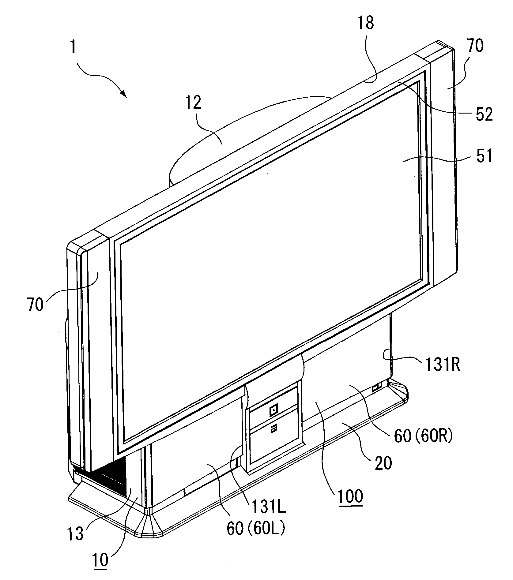
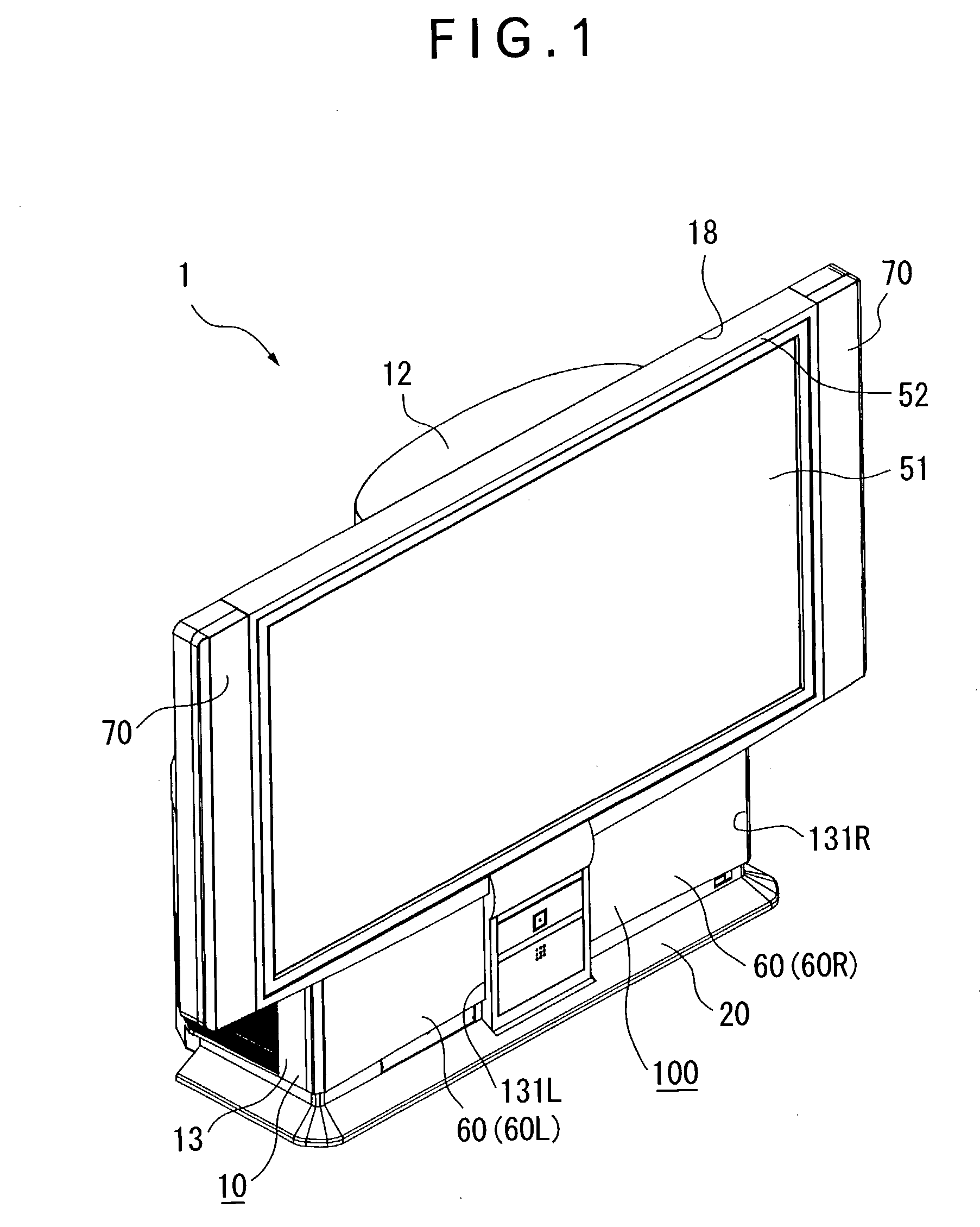
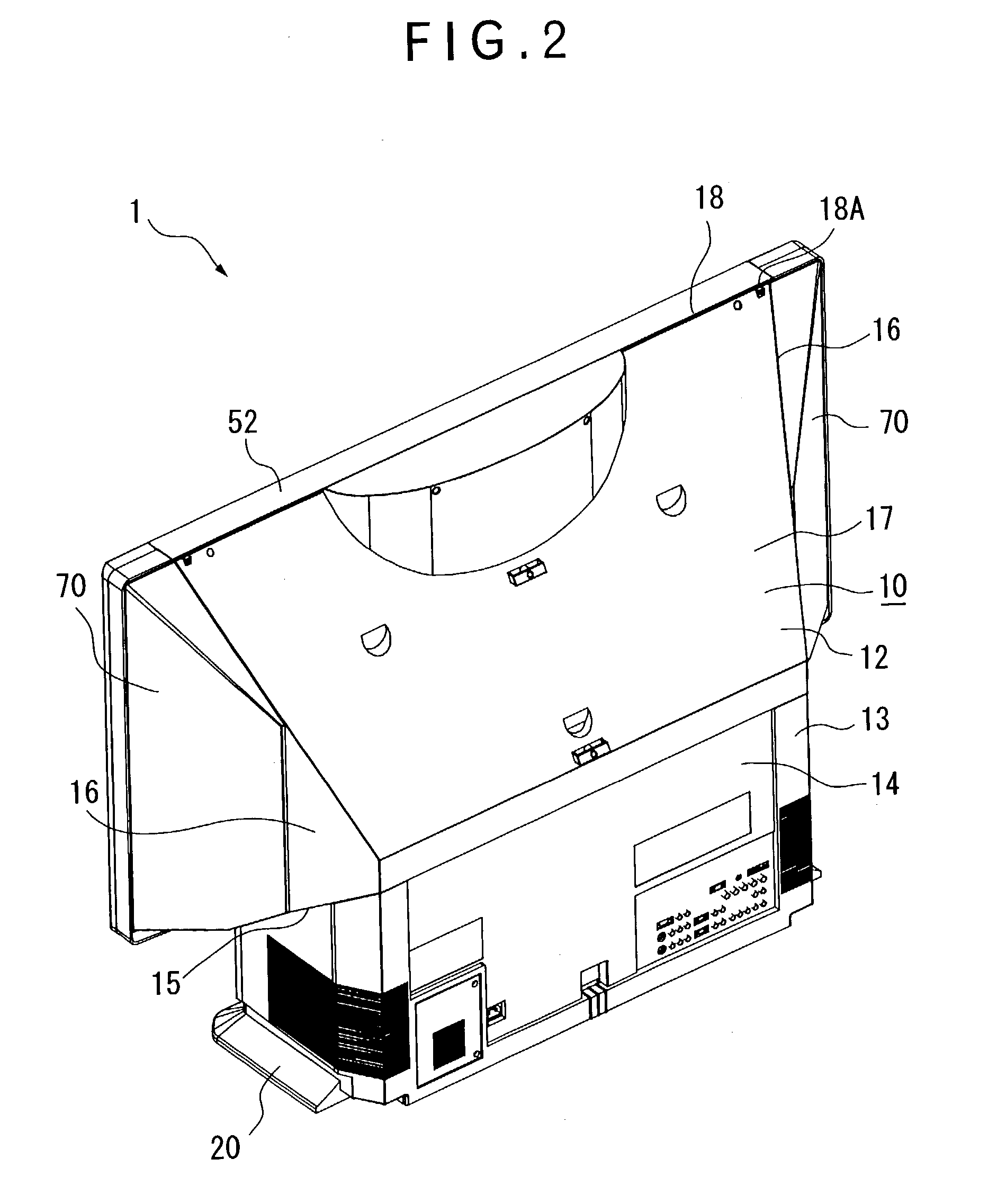
[0042] FIG. 1 is a perspective view seen from front side of a rear projector 1 according to an aspect of the present invention. FIG. 2 is a perspective view of the rear projector 1 seen from rear side thereof. FIG. 3 is an exploded perspective view of the rear projector 1 seen from rear side, which specifically shows the rear projector 1 with a back cover 14 being removed from FIG. 2. FIG. 4 is an exploded perspective view of the rear projector 1 seen from lower side. FIG. 5 is a vertical cross section showing the rear projector 1.

[0043] A primary arrangement of the rear projector 1 will be described below with reference to FIGS. 1 to 5.

[0044] As shown in FIGS. 1 to 5, the rear projector 1 modulates a light beam irradiated by a light source in accordance with image information to form an optical image, and enlarges and projects t...


PUM


Abstract

A rear projector (1) has a lower cabinet (13) disposing an image generator and an upper cabinet (12) for a screen body (51) to be mounted, two woofer boxes (60) being mounted on the front side of the lower cabinet (13) and high-pitched sound speaker boxes (70) being respectively mounted on the right and left lateral sides of the upper cabinet (12), so that, since the woofer box (60) is disposed in the lower cabinet (13), vibration is not easily transferred to a screen body (51) on the upper cabinet (12) and a reflection mirror inside the upper cabinet (12), thus avoiding flicker of the image on the screen body (51) even when great volume of sound is outputted by the woofer box (60).

Description

[0001] 1. Field of the Invention[0002] The present invention relates to a rear projector having an image generator including an optical device for modulating a light beam irradiated by a light source to form an optical image in accordance with image information and a projection optical system for enlarging and projecting the optical image, a sound output for outputting sound in accordance with sound information inputted together with the image information, a box-shaped casing for disposing the image generator, and a screen exposed on one of the lateral sides of the casing onto which the optical image formed by the image generator is projected, and a producing method thereof.[0003] 2. Description of Related Art[0004] Recently, a rear projector has come to be used in the field of home theater etc. Such rear projector has an image generator for generating a projection image, a box-shaped casing disposing the image generator and a reflection mirror for reflecting the projected image and...

Claims


Application Information

Patent Timeline
Patent Type & Authority Applications(United States)
IPC IPC(8): G03B21/10G03B21/22H04N5/64H04N5/74
CPCG03B21/22
Inventor ARAI, JUNYAMADA, HARUYOSHI
Owner SEIKO EPSON CORP
Learn More