Convertible ski-supported vehicle

a technology of skis and skis, applied in the field of skis, can solve the problems of difficult, if not impossible, to steer a snowmobile, skis that are subject to excessive wear and need to be replaced more frequently, and skis that are difficult to glide across gravel, hardtops, or other non-snow surfaces

Inactive Publication Date: 2003-12-04
OUELLETTE MICHAEL J
View PDF18 Cites 9 Cited by
  • Summary
  • Abstract
  • Description
  • Claims
  • Application Information

AI Technical Summary

Benefits of technology

[0012] The objects are achieved by providing a road wheel unit having one or more wheels that is permanently or semi-permanently installed on the ski of a conventional snowmobile so as to provide easily deployable or retractable wheels, as the conditions require. In a retracted position, i.e. the standard snowmobile mode of operation, the wheel is carried alongside the ski, raised above the gliding surface of the ski. In a deployed position, the wheel is lowered, so that the weight of the machine is supported by the wheel. In this deployed position, the wheel unit holds the ski above the rolling surface of the wheel and allows the snowmobile to ride on wheels and the conventional endless track at the rear end. In the deployed mode, the snowmobile remains readily steerable with the handlebars, and the carbide runners on the ski surfaces are not subject to excessive wear. Ideally, the wheel or wheels of the wheel unit are easily detachable from the mounting means, leaving the mounting means permanently installed on the vehicle, without impairing the functionality of the skis. As mentioned above, a wheel unit has one or more wheels. Generally, at least one wheel is mounted on each of the two skis of the snowmobile and, thus, the term "wheels" is generally used hereinafter, although it is understood that, depending on the type of wheel unit, only one wheel may be mounted on a ski.
[0015] The deployment mechanism is ideally a relatively simple mechanical shifting and locking mechanism that allows the operator to easily shift the wheel unit between a deployed wheel position and a retracted wheel position and to securely lock the wheel unit in the respective position. One deployment mechanism that is suitable includes a side rail that is shiftably attached to the wheel unit and a latching mechanism for latching the wheel unit into a first or deployed position and into a second or retracted position. For example, a latch is mounted on the ski or on the wheel unit and the wheel unit locked into position by catching the latch in the first position or in the second position on the rail. The first and second position may be connected by a groove and the latch itself may be a pin that is captured at one end in the groove and is slidably movable into the first position or into the second position, where it is secured against unintentional release.

Problems solved by technology

A disadvantage of snowmobiles is that the skis don't readily glide across gravel, hardtop, or other non-snow surfaces.
This makes it difficult, if not impossible, to steer a snowmobile because the skis do not respond properly to the steering operations initiated at the handlebars.
Furthermore, when a snowmobile is driven or dragged across a non-snow surface, the carbide runners on the skis are subject to excessive wear and must be replaced more frequently, depending on how often a snowmobile travels across a non-snow surface.
This inability to steer snowmobiles on surfaces other than snow and ice makes it difficult for people to maneuver their snowmobiles across roadways, driveways, onto ferries, etc.
Also, now that such lengthy trips are being undertaken with snowmobiles, the presence of snow along the entire route is not guaranteed, and consequently, snowmobiles are being required more and more frequently to travel some distance across surfaces other than snow or ice.
Now, however, with the need to travel several miles along a roadway to get to a filling station, the inability to steer a snowmobile has become a major obstacle in the logistics and the enjoyment of the sport.
Both methods of converting the snowmobile to a wheeled vehicle involve a fair amount of work.
Thus, such conversion kits are not generally an acceptable solution to the problem of having to change in relatively quick succession back and forth between a vehicle that rides on skis and one that rides on wheels, as happens when traveling over gravel or hardtop or other surface other than snow or ice to fill the gas tank or to load onto a ferry.

Method used


Image

  • Convertible ski-supported vehicle
  • Convertible ski-supported vehicle
  • Convertible ski-supported vehicle

Examples


Embodiment Construction

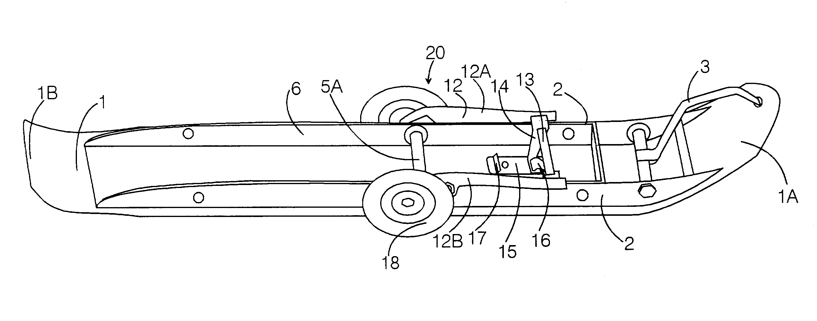
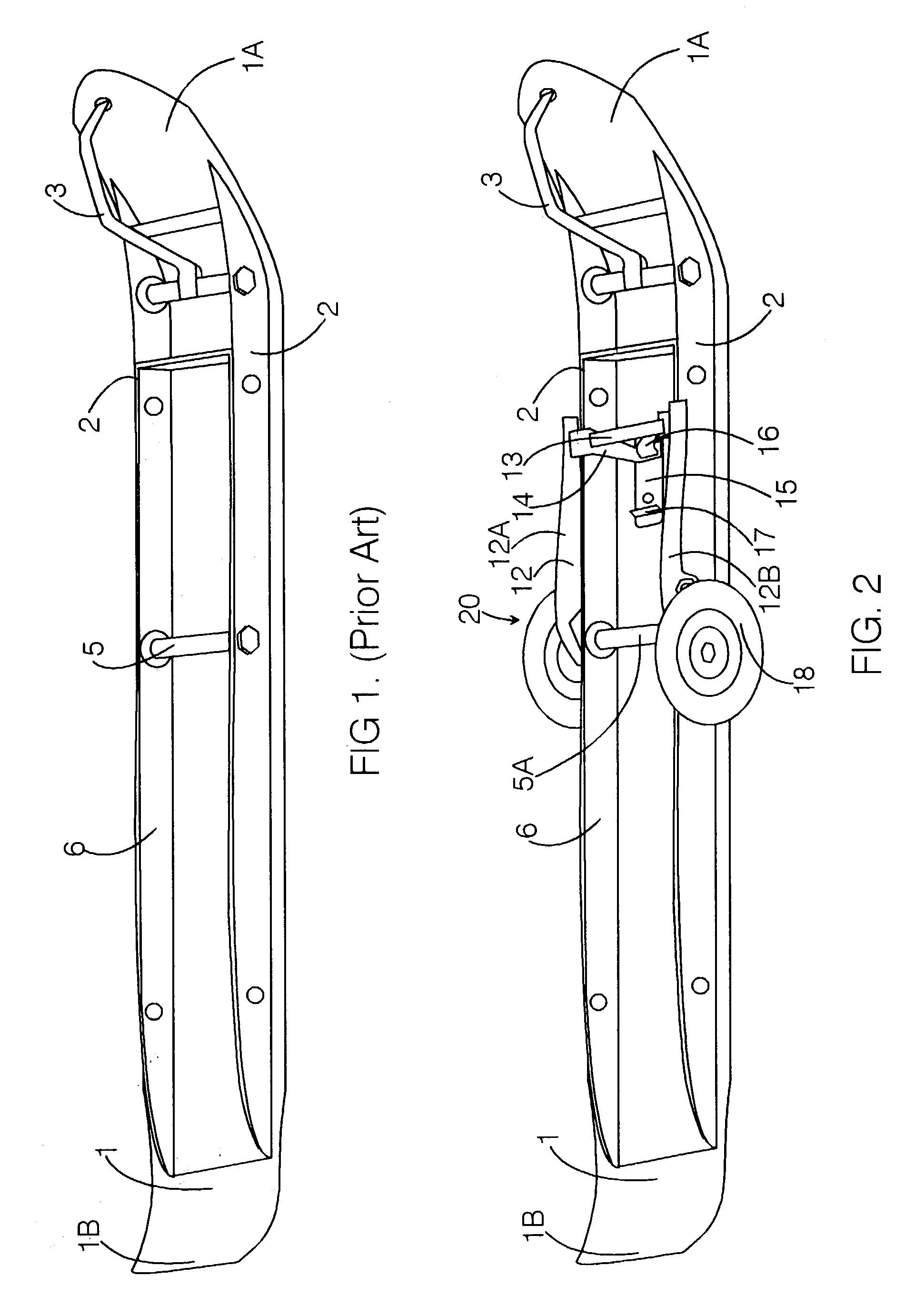
[0048] FIG. 1 shows a conventional snowmobile ski comprising a ski 1 having ski sides 2, a lifting handle 3 disposed at a front end 1A of the ski, and a reinforcing liner 6. A kingpin 5 is mounted in the ski 1. With the particular ski shown, a spindle (not shown) mounts on the kingpin 5 to attach the ski 1 to the snowmobile. The present invention is a wheel unit that is mountable on the ski 1, and is either directly mountable on the kingpin 5 or on a side 2 of the ski 1. It is noted here that a reference designation assigned to a particular element of the invention is maintained hereinafter throughout the description, even if the element is used in more than one embodiment of the invention.

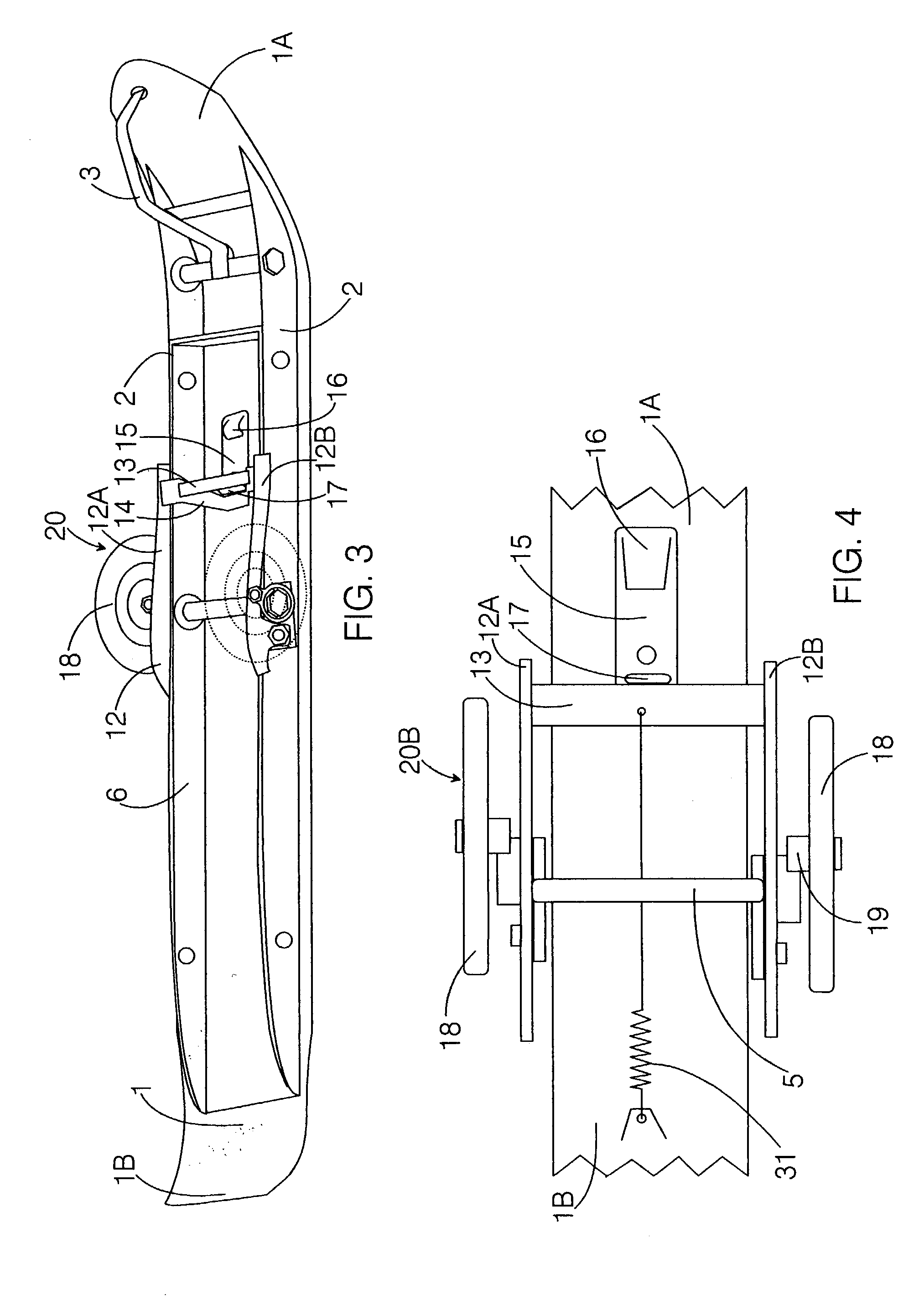
[0049] FIG. 2 shows an embodiment of a kingpin-mounted wheel unit 20 according to the invention that has been assembled on the ski 1. As shown in this FIG. 2, the wheel unit 20 is in a deployed position. The wheel unit 20 comprises a deployment mechanism that includes a movable frame 12 formed by ...


PUM


Abstract

Universal wheel unit for mounting one or more wheels on the ski of a snowmobile. The wheel unit is a separate assembly that is detachably mountable on the ski or is an integral component of the ski. When retrofitting skis, the wheel unit is mountable on the kingping, on the side wall, or on the saddle. Wheels are readily deployable or retractable as ground surface conditions require, and allow the snowmobile to be driven over gravel, dirt, and hardtop surfaces, while maintaining steerability with the handlebars.

Description

[0001] This application is, a Continuation-in-Part (CIP) of U.S. Patent Application 09 / 818,058, filed on Mar. 26, 2001, and of Continuation-in-Part Application 10 / 223,718, filed on Sep. 3, 2002.BACKGROUND INFORMATION[0002] 1. FIELD OF THE INVENTION[0003] The invention relates to the field of ski-supported vehicles. More particularly, the invention relates to snowmobiles equipped with wheels that will allow the snowmobile to travel readily over surfaces not covered with snow or ice.[0004] 2. DESCRIPTION OF THE PRIOR ART[0005] Snowmobiles are vehicles that are constructed to travel across snow and ice. As is generally known, the snowmobile is driven by an endless drive track arranged at the rear end of the underside of the snowmobile. The front end of the snowmobile is supported and rides along two skis, which glide across the surface of the snow or ice. The skis typically have a carbide runner that runs along a portion of the bottom surface of the ski, to help keep the snowmobile tra...

Claims


Application Information

Patent Timeline
Patent Type & Authority Applications(United States)
IPC IPC(8): B62B13/18B62K13/00B62M27/00B62M27/02
CPCB62B13/18B62K13/00B62M2027/025B62M27/02B62M27/00
Inventor OUELLETTE, MICHAEL J.
Owner OUELLETTE MICHAEL J
Why Eureka
Try Eureka