
Locking/unlocking mechanism for headrest

a technology for locking and unlocking the headrest, which is applied in the field of headrest locking and unlocking the mechanism, can solve the problems of increasing the causing a large damage to the user, and requiring an increased number of parts and fittings

Inactive Publication Date: 2003-12-04
TACHI S CO LTD
View PDF0 Cites 25 Cited by
  • Summary
  • Abstract
  • Description
  • Claims
  • Application Information

AI Technical Summary

Benefits of technology

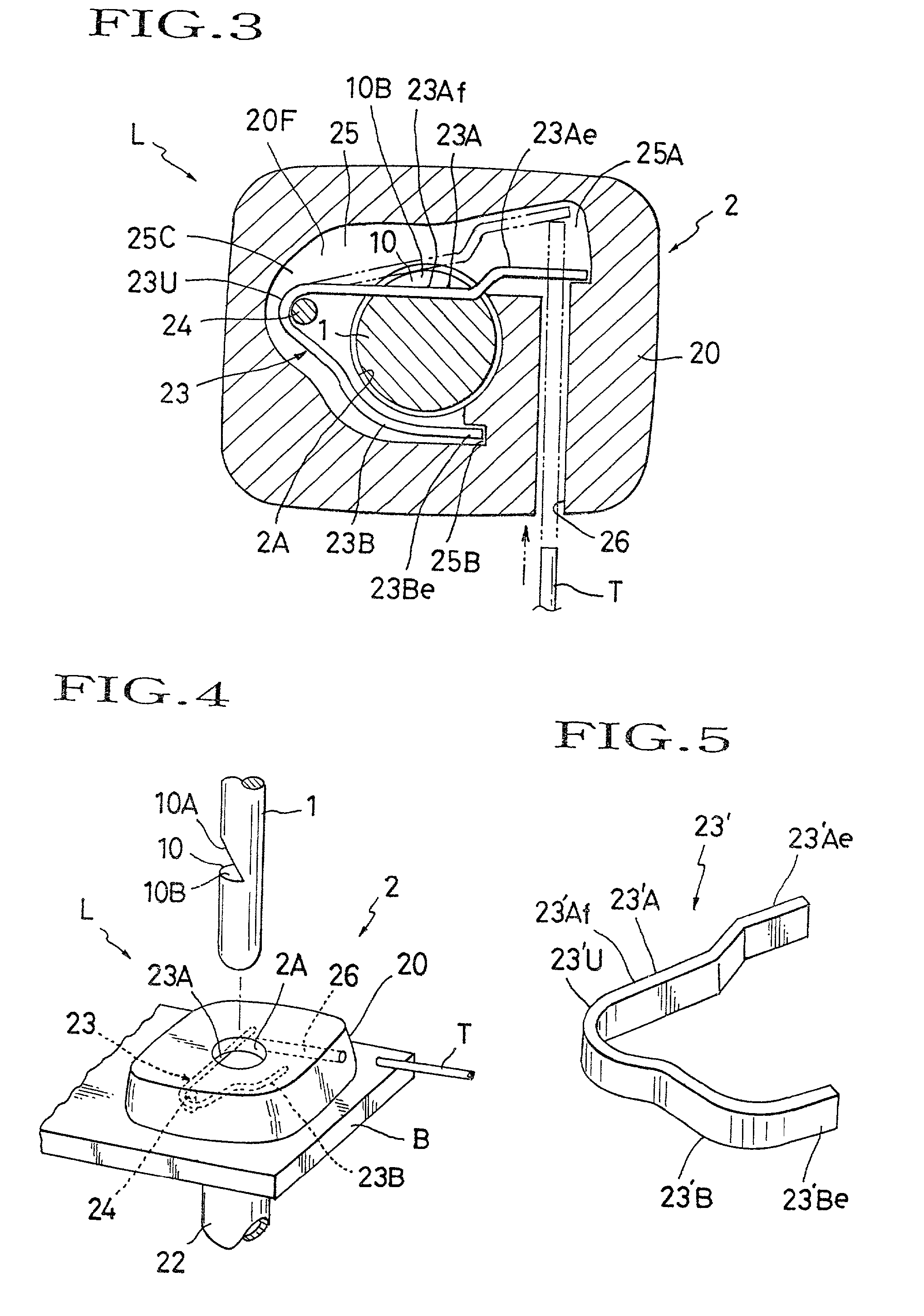
[0011] a hole formed in the headrest holder in such a manner as to allow an unlocking tool to be inserted therethrough to contact and bend the engagement portion of elastic lock element resiliently in a direction away from the through-bore of headrest holder, thereby allowing for disengagement of the engagement portion from the stopper notch.
[0012] Accordingly, this mechanism allows for direct use of an ordinary stopper notch of headrest stay, and further, one elastic lock element and one unlocking hole are only provided in the headrest holder as a principal element for locking / unlocking relation with such stopper notch, thus not requiring any other separate mechanical parts found in the prior art. This very simplified structure not only insures a failure-free unlocking effect, but also achieve a high reduction of costs and parts involved.

Problems solved by technology

But, this is not always favorable because it is troublesome to insert the removed headrest or headrest stay in the headrest holder when a user sits on the seat, and, in the case of traffic accident including a collision, a great force generated thereby may draw and separate the headrest or headrest stays away from the headrest holders, resulting in a great damage to the user.
This sort of headrest removal preventive mechanism is not designed to permit for removal of the headrest, and therefore, in the case where the headrest needs to be removed from the seat back, an unlocking arrangement will be required to release the lock plate of the headrest removal preventive mechanism from the notch formed in the headrest stay.
However, such unlocking arrangement requires the two springs as well as specially designed mechanical elements and fittings between the springs and lock plate, which has been found defective in rendering the structure more complicated and requiring an increased number of parts and fittings.

Method used


Image

  • Locking/unlocking mechanism for headrest
  • Locking/unlocking mechanism for headrest
  • Locking/unlocking mechanism for headrest

Examples


Embodiment Construction

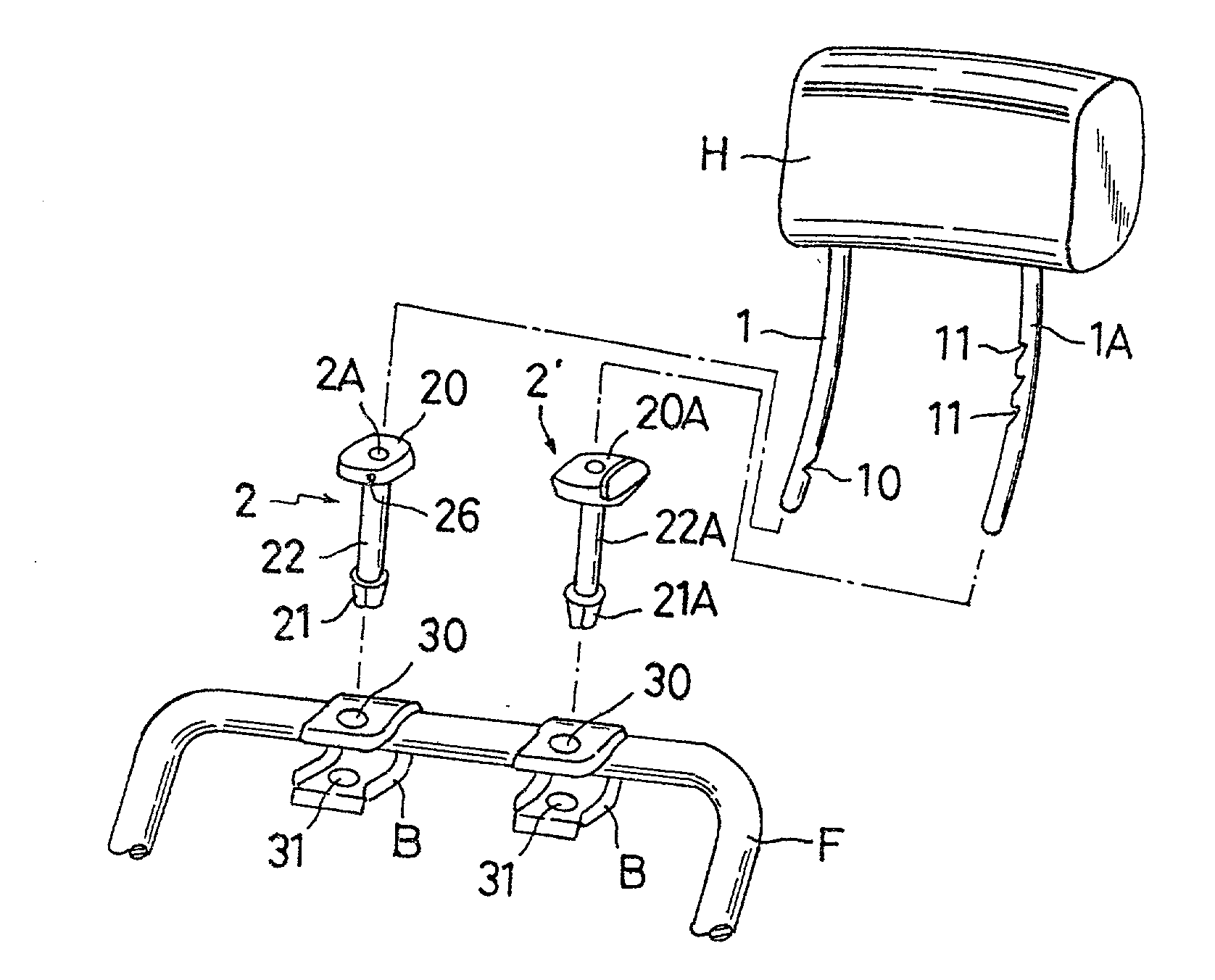
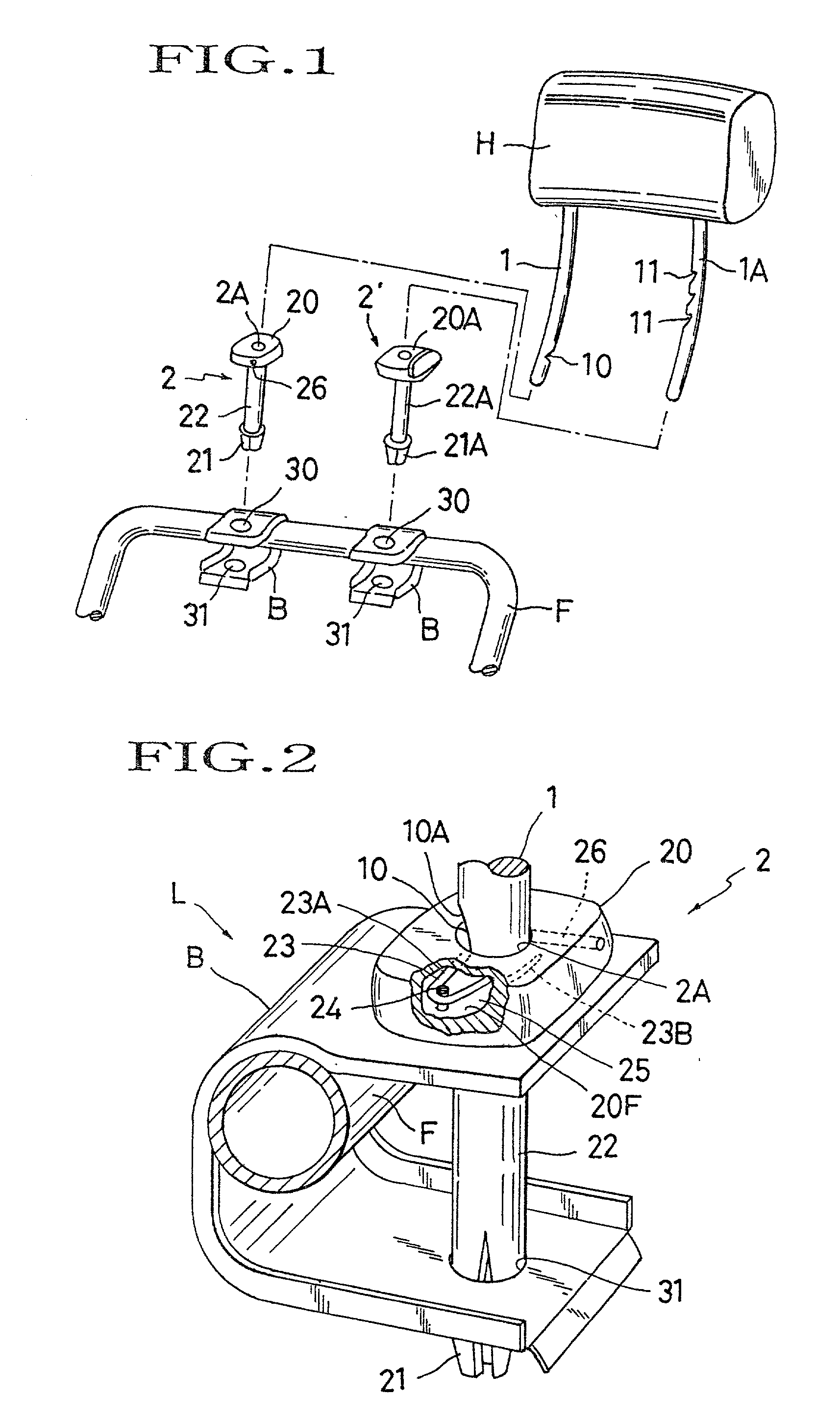
[0020] Referring to FIGS. 1 through 5, there is illustrated one exemplary mode of locking / unlocking mechanism for a headrest to be used on an automotive seat, in accordance with the present invention, the mechanism being generally designated by (L).

[0021] As shown in FIG. 1, for instance, upon the top of a seat back frame (F), a pair of securing brackets (B) (B) are fixedly provided, each of which is formed with a pair of upper and lower through-holes (30) (31) therein. While not shown, it is to be understood that all those seat back frame (F) and brackets (B) are provided within a seat back of an automotive seat by enclosing them with a suitable foam padding and cover material or other suitable upholstery, as is known in the art.

[0022] On the other hand, a headrest (H), which is to be used on the seat back of automotive seat for supporting a head of passenger, has a pair of first and second headrest stays (1) (1A) projecting downwardly therefrom. The first headrest stay (1) is show...


PUM


Abstract

A locking / unlocking mechanism for headrest, which is provided in a headrest holder in which a headrest stay is slidably inserted, comprising: an elastic lock element secured in the headrest holder; and an unlocking hole so formed in the headrest holder as to lead to the elastic lock element. The elastic lock element can be engaged in an ordinary stopper notch formed in the headrest stay to prevent removal of the headrest from a seat back of seat, but can be disengaged therefrom by inserting a tool into the unlocking hole so as to resiliently bend the elastic lock element away from the stopper notch, thereby allowing removal of the headrest from the seat back. Preferably, the elastic lock element is formed in a generally "U" shape.

Description

[0001] 1. Field of the Invention[0002] The present invention relates to a mechanism for locking and unlocking a headrest for automobile.[0003] 2. Description of Prior Art[0004] Normally, a headrest for use with an automotive seat has a pair of headrest stays projecting donwardly therefrom. Via those two headrest stays, the headrest is mounted and supported on the seat back of the automotive seat. In most cases, a pair of headrest holders are utilized to support the respective two headrest stays upon a seat back frame which is provided in the seat back. Each headrest holder is fixed on the top of seat back frame and of a cylindrical shape allowing insertion of the corresponding headrest stay therein. Further, a headrest vertical adjustment mechanism is provided between the headrest stays and headrest holders so that the headrest can be adjustably raised and lowered via the headrest holders according to the physique and head position of a user sitting on the seat.[0005] Due to the cyl...

Claims


Application Information

Patent Timeline
IPC IPC(8): B60N2/48
CPCB60N2/4817B60N2/4814B60N2/815B60N2/818
Inventor NEMOTO, AKIRAICHIKAWA, HIROAKI
Owner TACHI S CO LTD
Learn More