Display device

a display device and flat panel technology, applied in the direction of discharge tube luminescnet screens, electrode systems, electric discharge tubes/lamps, etc., can solve the problems of deteriorating color purity and pushing up the production cost of display devices, and achieves high partitions, prevent color purity deterioration, and simple procedure

Inactive Publication Date: 2007-02-08
JAPAN DISPLAY INC
View PDF6 Cites 6 Cited by
  • Summary
  • Abstract
  • Description
  • Claims
  • Application Information

AI Technical Summary

Benefits of technology

[0018] The objects of the present invention are to provide a high-quality display device which prevents deterioration of color purity by use of a black matrix whose openings have sufficiently high partitions by a simple procedure; and also to provide a method for producing the display device.

Problems solved by technology

When the opening wall has an insufficient height (which means the partition between the openings has an insufficient height, or the black matrix has an insufficient thickness), part of the fluorescent substance in an opening may overflow into an adjacent opening, resulting in deteriorated color purity.
This needs time-consuming works to form the black matrix, and larger production facilities as the panel size becomes larger, pushing up the display device production cost.

Method used


Image

  • Display device
  • Display device
  • Display device

Examples


example 1

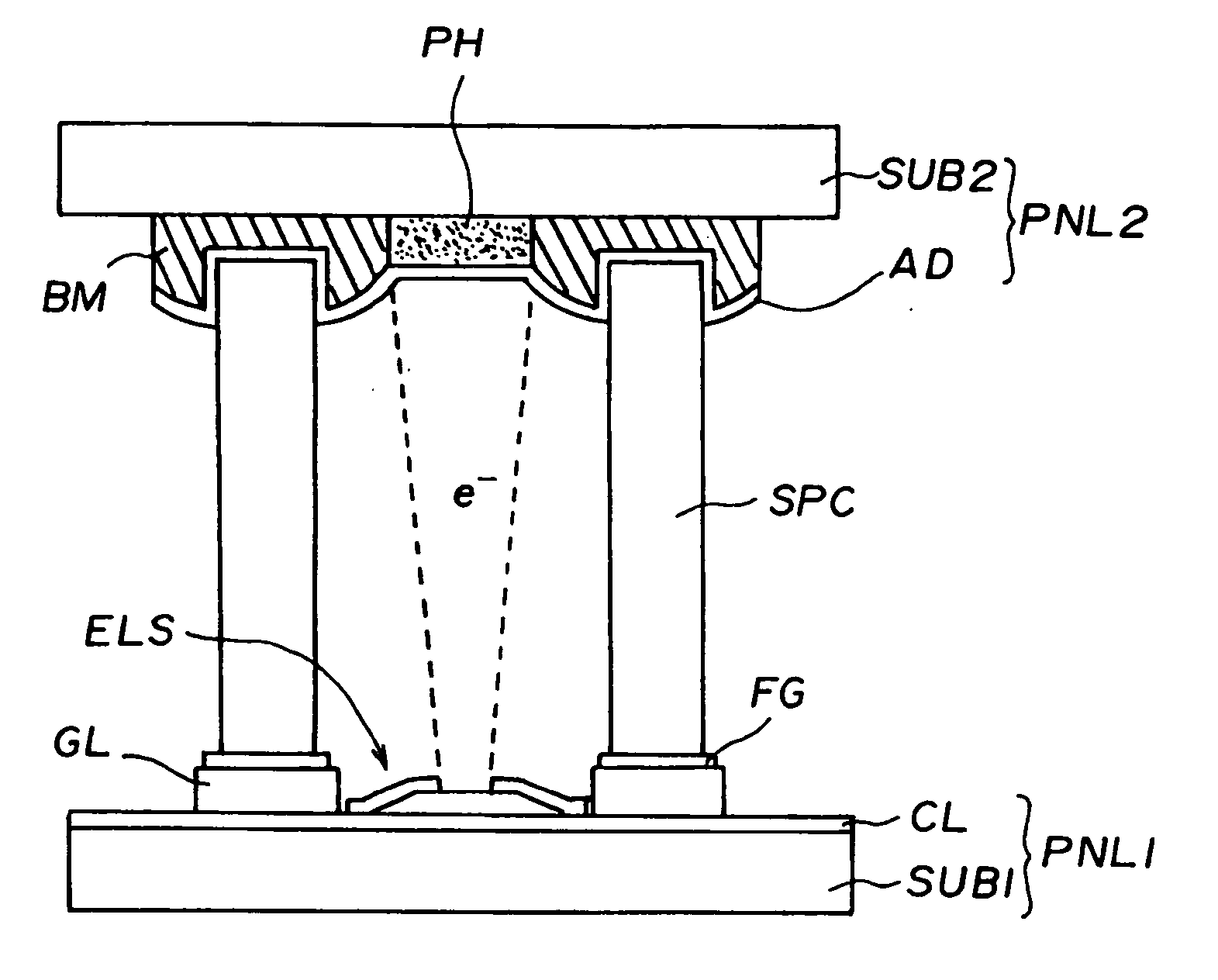
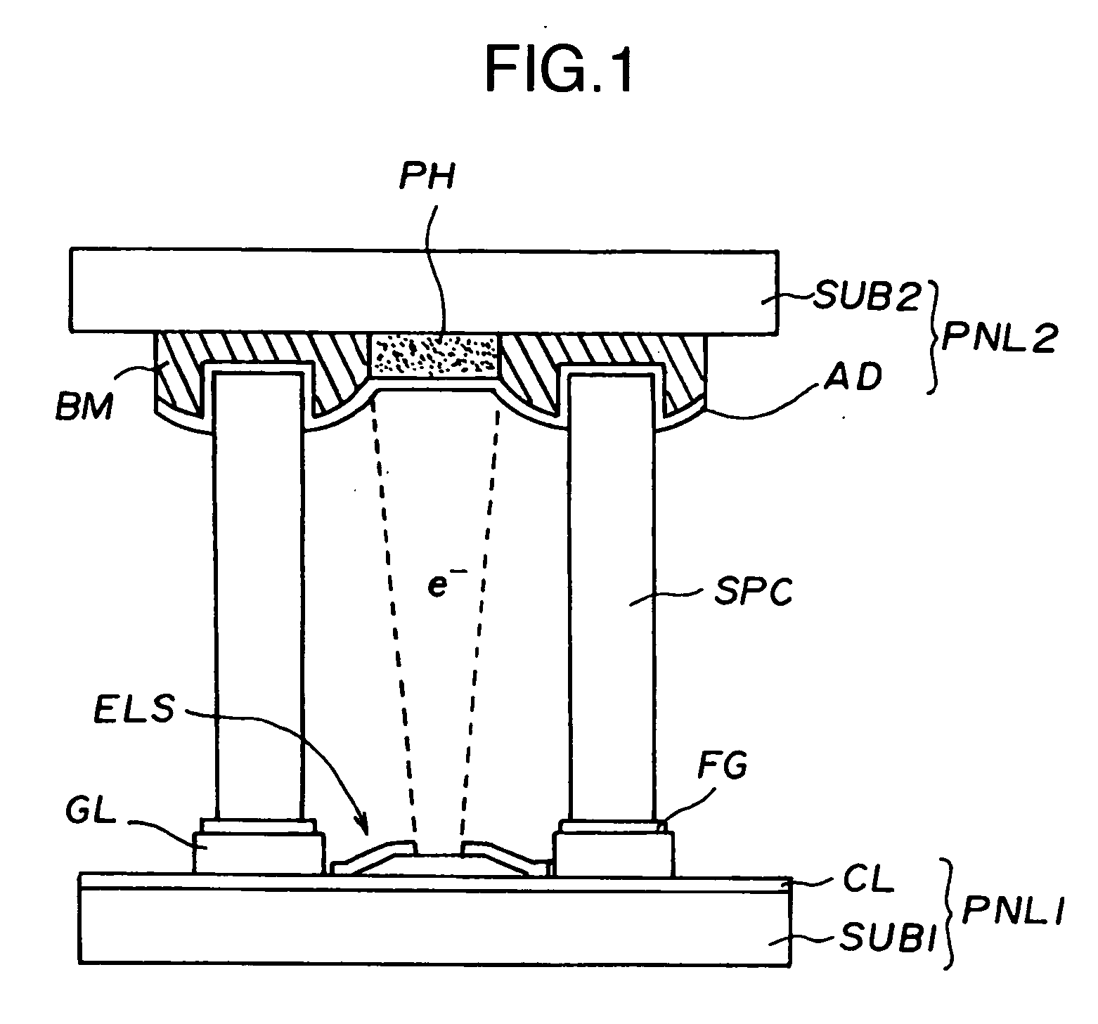
[0052]FIG. 1 is a cross-sectional view schematically illustrating the display device of the present invention, prepared in EXAMPLE 1, around a pixel. In the display device illustrated in FIG. 1, the rear substrate SUB 1 which constitutes the rear panel PNL 1 has, on the inner surface, the signal lines (data lines or cathode lines) CL and scanning lines (gate lines or gate electrode lines) GL, these lines normally intersecting each other at right angles, and the electron sources ELS located at near the intersections of these lines. The electron source ELS structure is illustrated in FIG. 8.

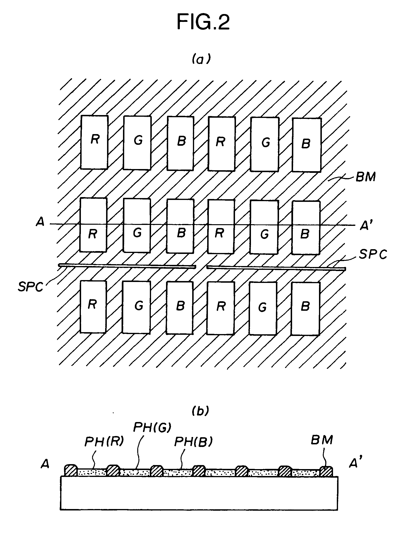
[0053] The front substrate SUB 2 which constitutes the front panel PNL 2 has, on the inner surface, the black matrix BM having openings filled with a fluorescent substance, where the substrate SUB 2 is made of a glass plate. The black matrix BM is formed by printing / calcinating an electroconductive black glass paste, which is composed of glass incorporated with a black additive and electroconducti...


PUM


Abstract

It is an object to provide a high-quality display device which prevents deterioration of color purity by use of a black matrix whose openings have sufficiently high partitions by a simple procedure. The black matrix BM is formed using an electroconductive black glass, comprising a glass incorporated with a black additive and electroconductive filler. The glass is mainly composed of V2O5, SnO2, Bi2O3, Ag2O or a combination thereof.

Description

FIELD OF THE INVENTION [0001] The present invention relates to a self-luminous, flat-panel display device which utilizes emission of electrons into a vacuum, in particular display device provided with a display panel comprising a rear panel and front panel, where the rear panel is composed of a rear substrate having electron sources which emit electrons by field emission, and the front panel is composed of a front substrate having a fluorescent substance excited by electrons from the rear panel to emit a different color and positive electrodes working as electron accelerator electrodes, with spacers arranged to keep a given gap between the rear and front panels (the spacer may be hereinafter referred to as gap-keeping member or partition). BACKGROUND OF THE INVENTION [0002] Color cathode-ray tubes have been widely used for high-luminance, high-fineness display devices. Recently, however, demands for displays which have high-luminance, high-fineness characteristics and, at the same t...

Claims


Application Information

Patent Timeline
Patent Type & Authority Applications(United States)
IPC IPC(8): H01J63/04H01J1/62H01J9/26H01J9/32
CPCH01J31/127H01J9/2278
Inventor SHIONO, OSAMUMIYATA, MOTOYUKISAWAI, YUICHINAITOU, TAKASHIKODERA, YOSHIETOJO, TOSHIOSAGAWA, MASAKAZUKUSUNOKI, TOSHIAKI
Owner JAPAN DISPLAY INC
Why Eureka
Try Eureka