Method for initializing position with an encoder

Inactive Publication Date: 2003-12-04
VISTEON GLOBAL TECH INC
View PDF23 Cites 72 Cited by
  • Summary
  • Abstract
  • Description
  • Claims
  • Application Information

AI Technical Summary

Problems solved by technology

However, the quadrature encoder signal can only p

Method used


Image

  • Method for initializing position with an encoder
  • Method for initializing position with an encoder
  • Method for initializing position with an encoder

Examples


example

[0037] Two signals A and B are presented to the microcontroller and inverted with respect to the signals on the module connector. Together, these two signals form a digital quadrature incremental encoder signal. The two signals are used to determine differential position and direction of the rotor or steering wheel. The up / down counter timer peripheral in the microcontroller is used to decode the quadrature inputs and convert them to an increasing count (turn to the right) or decreasing count (turn to the left). This count which corresponds to the rotor or steering wheel position can be read directly from the register. Since the rising and falling edges for both signals A and B are counted, there are four counts per encoder line.

[0038] In a preferred embodiment of the quadrature encoder, a rotor position encoder is coupled with a rotor position sensor interface. A corresponding signal typically has a frequency of 0-50 khz and a resolution of 0.09 rotor degrees for each count. A typi...


PUM


Abstract

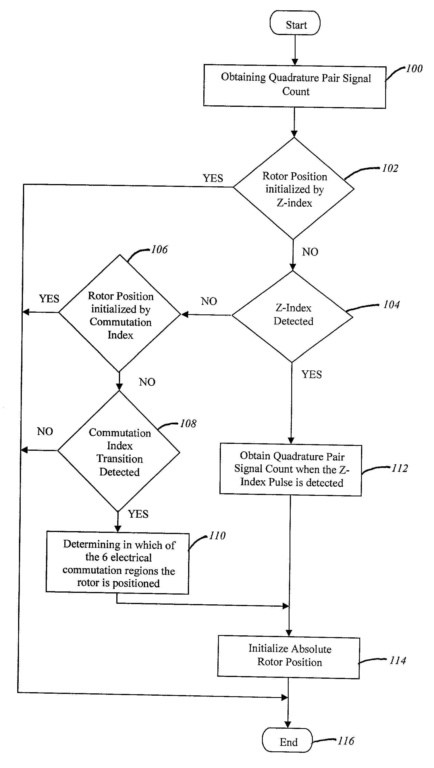
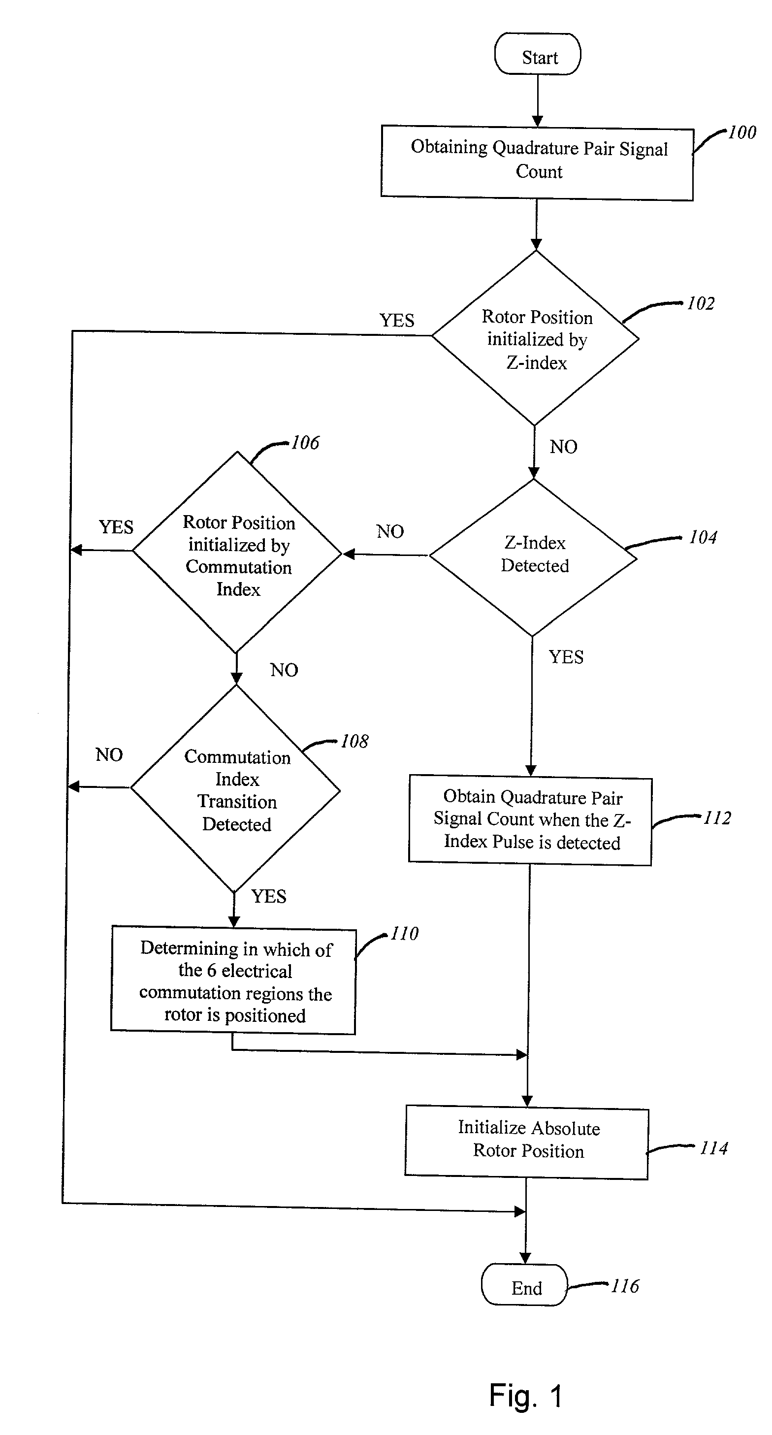
A method for detecting an absolute rotational position of an electromechanical device or the at least one component thereof comprising determining a first absolute position of the electromechanical device or the at least one component thereof based on a commutation index signal, obtaining a Z-index signal, and determining a second absolute position of the electromechanical device or the at least one component thereof based on the Z-index signal. The method initially determines a coarse rotational position of the electromechanical device such as a rotor or steering wheel based on the commutation index signal. When a device's position is first initialized by a commutation index signal before the Z-index pulse is detected, the device's position is re-initialized upon detection of the Z-Index pulse to provide a more accurate absolute device rotational position.

Description

[0001] The invention generally relates to a method for determining the absolute rotational position of an electromechanical device. In particular, the invention relates to a method for determining the absolute position of an electromechanical device using a coarse and a fine index.DESCRIPTION OF THE RELATED ART[0002] Mechanical devices normally require the control of linear or rotational force, speed, and / or position. Such control may be implemented using hydraulics, pneumatics, electromechanical and mechanical devices. Examples of electromechanical devices are AC motors, DC motors, stepper motors, and actuators. DC motors are used to convert electrical energy into rotational mechanical energy. The speed of these motors may be controlled using open-loop and closed-loop control systems. In an open-loop system, the real-time, present position of the rotor is not monitored continuously.[0003] In a typical closed-loop system, the position of the rotor is fed back into the control proces...

Claims


Application Information

Patent Timeline
IPC IPC(8): G01D5/245H03M1/20H03M1/30H03M1/64
CPCG01D5/2457H03M1/206H03M1/645H03M1/308H03M1/303
Inventor FLOROS, JOHN H.SARAFOPOULOS, NICKJORDAN, PAUL T.
Owner VISTEON GLOBAL TECH INC
Why Eureka
Try Eureka