Control circuit for dimming fluorescent lamps

a technology for controlling circuits and fluorescent lamps, which is applied in the direction of electric variable regulation, process and machine control, instruments, etc., can solve the problems of reducing the life of the circuit, cumbersome structure, and bulky weight of the circuit,

Inactive Publication Date: 2003-12-11
LUSA LIGHTING
View PDF0 Cites 20 Cited by
  • Summary
  • Abstract
  • Description
  • Claims
  • Application Information

AI Technical Summary

Problems solved by technology

The disadvantages of the prior art circuit illustrated in FIG. 1 are inherent in its design.
The system uses a high inductor (e.g., 1 Henry) which will result in a structure which is cumbersome, bulky and heavy.
The primary disadvantage of the prior art circuit shown in FIG. 1 is that it cannot be used to dim the light emitted from a fluorescent lamp.
The disadvantage of the prior art circuit illustrated in FIG. 2 is that

Method used


Image

  • Control circuit for dimming fluorescent lamps
  • Control circuit for dimming fluorescent lamps
  • Control circuit for dimming fluorescent lamps

Examples


Embodiment Construction

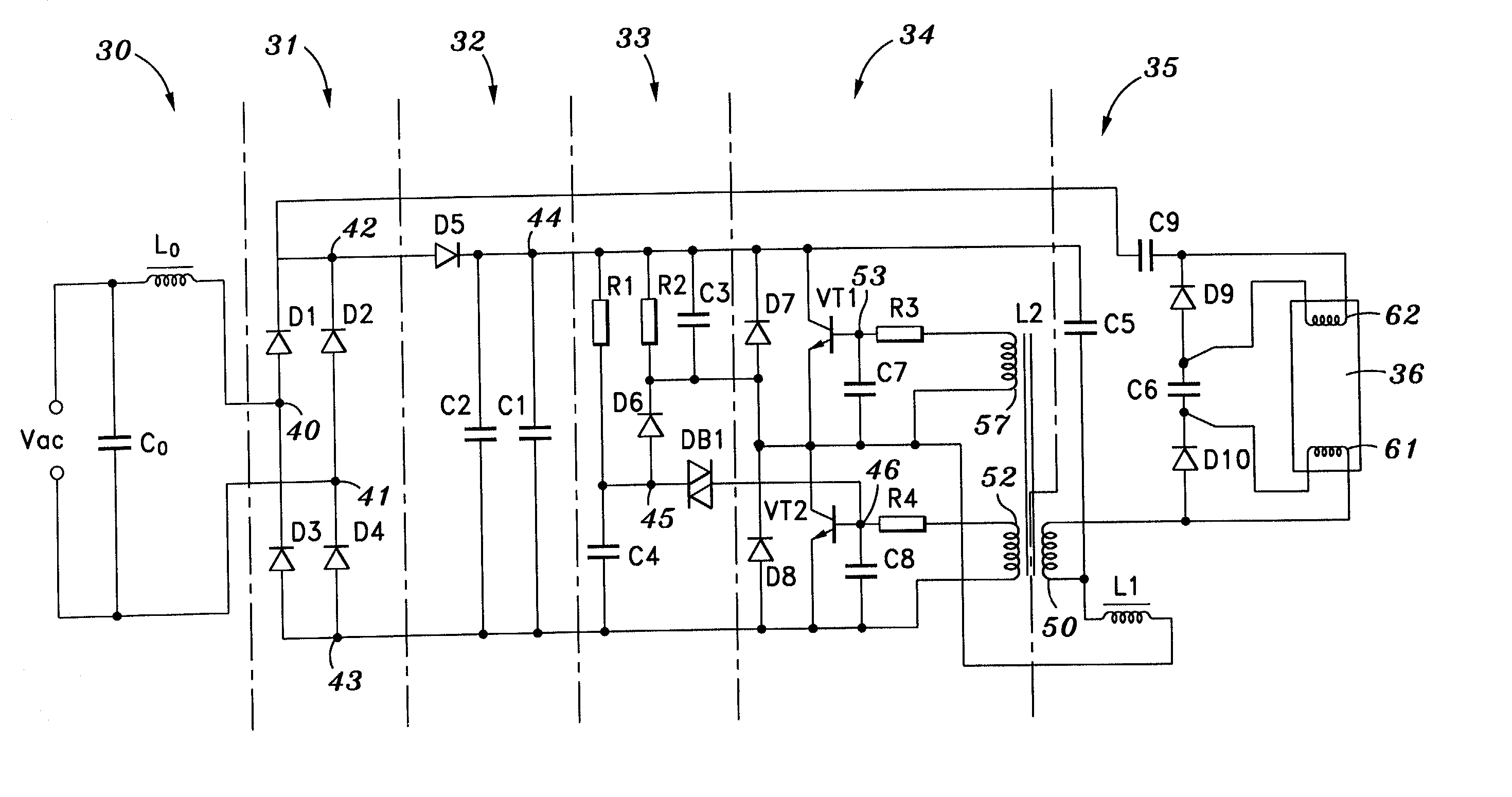
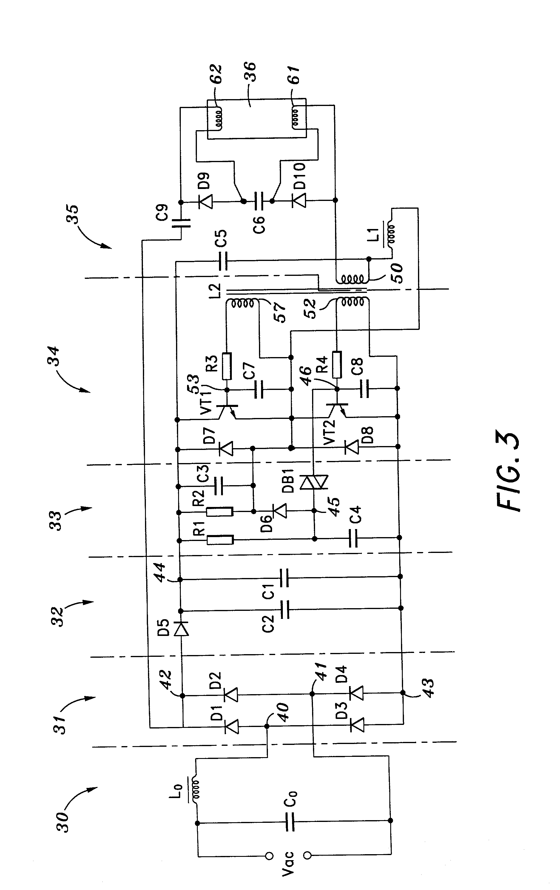
[0025] The present invention constitutes a control circuit or ballast which is used as a current limiting element necessary because of the structure of fluorescent lamps. A fluorescent lamps operates as a voltage limiting component, i.e., the voltage drop across the fluorescent lamp is independent of the input supply voltage. The fluorescent lamp ballast serves three functions. Firstly, it creates a voltage which is sufficiently high to start or otherwise turn the fluorescent lamp on. Secondly, the ballast limits the alternating current to the fluorescent lamp once it has been started. Thirdly, the ballast provides voltage to the filaments of the fluorescent lamp.

[0026] An understanding of the preferred embodiment of the present invention can be best gained by reference to FIGS. 3 and 4. The electronic circuit shown in FIG. 3 may be divided into six segments. These consist of an electromagnetic interference (i.e., an EMI) filter 30, a diode bridge rectifier 31, a direct current powe...


PUM


Abstract

The present invention constitutes a control circuit which permits the dimming of the illumination emitted from a fluorescent lamp. A controllable source of alternating current power is converted to direct current utilizing a conventional diode bridge and power filter. The direct current signal is converted to a high frequency alternating current signal using a self-oscillating inverter circuit. The output of the inverter circuit is coupled to a resonance circuit. The lamp will be turned on when the output of the resonance circuit is increased until it exceeds the minimum voltage specified for the selected fluorescent lamp. A voltage doubler circuit powers the fluorescent lamp and permits the fluorescent lamp to be dimmed or otherwise remain illuminated when the input alternating power is reduced below that specified for normal operation of the fluorescent lamp.

Description

[0001] 1. Field of the Invention[0002] The present invention generally relates to the field of control circuits used to power fluorescent lamps and in particular to those circuits which permit the illumination of a fluorescent lamp to be dimmed in response to a reduction in input power.[0003] 2. Prior Art[0004] In order for a fluorescent lamp to illuminate, the voltage across the filaments thereof must be greater than the minimum voltage specified for the lamp. Under typical conditions, it is necessary for a lamp supply circuit to include a current limiting element. The fluorescent lamp itself acts as a voltage limiting component. The voltage across the filaments of a fluorescent lamp is independent of the power supply voltage and is determined by the power of the fluorescent lamp itself. Therefore, to illuminate a fluorescent lamp with conventional alternating current power (i.e., 115 volts / 60 Hz), a ballast or current limiting component is utilized.[0005] To turn on or illuminate ...

Claims


Application Information

Patent Timeline
IPC IPC(8): H05B41/282H05B41/298
CPCH05B41/2827Y02B20/185H05B41/2983Y02B20/00
Inventor BENENSOHN, SANFORD H.
Owner LUSA LIGHTING
Why Eureka
Try Eureka