Fixture for microscope component alignment

a technology for fixing microscope components and optical components, which is applied in the field of microscope optical component adjustment, can solve the problems of different locations of target mirrors, tedious and time-consuming processes, and inability to accurately locate the target mirror

Inactive Publication Date: 2003-12-11
SOLURIS +1
View PDF5 Cites 3 Cited by
  • Summary
  • Abstract
  • Description
  • Claims
  • Application Information

AI Technical Summary

Problems solved by technology

A drawback of the prior art alignment technique discussed above is that the location of the target mirror at the sample plane--which is used for adjustment of the objective lens--is different than the location of the target mirror at the objective lens port, i.e. the location used to align the illumination path and imaging path optical components.
Such a process is tedious and time consuming.
Also, it may not be possible to know for certain which component is responsible for the misalignment, so a repetitive sequence of steps is required.

Method used


Image

  • Fixture for microscope component alignment
  • Fixture for microscope component alignment
  • Fixture for microscope component alignment

Examples


Embodiment Construction

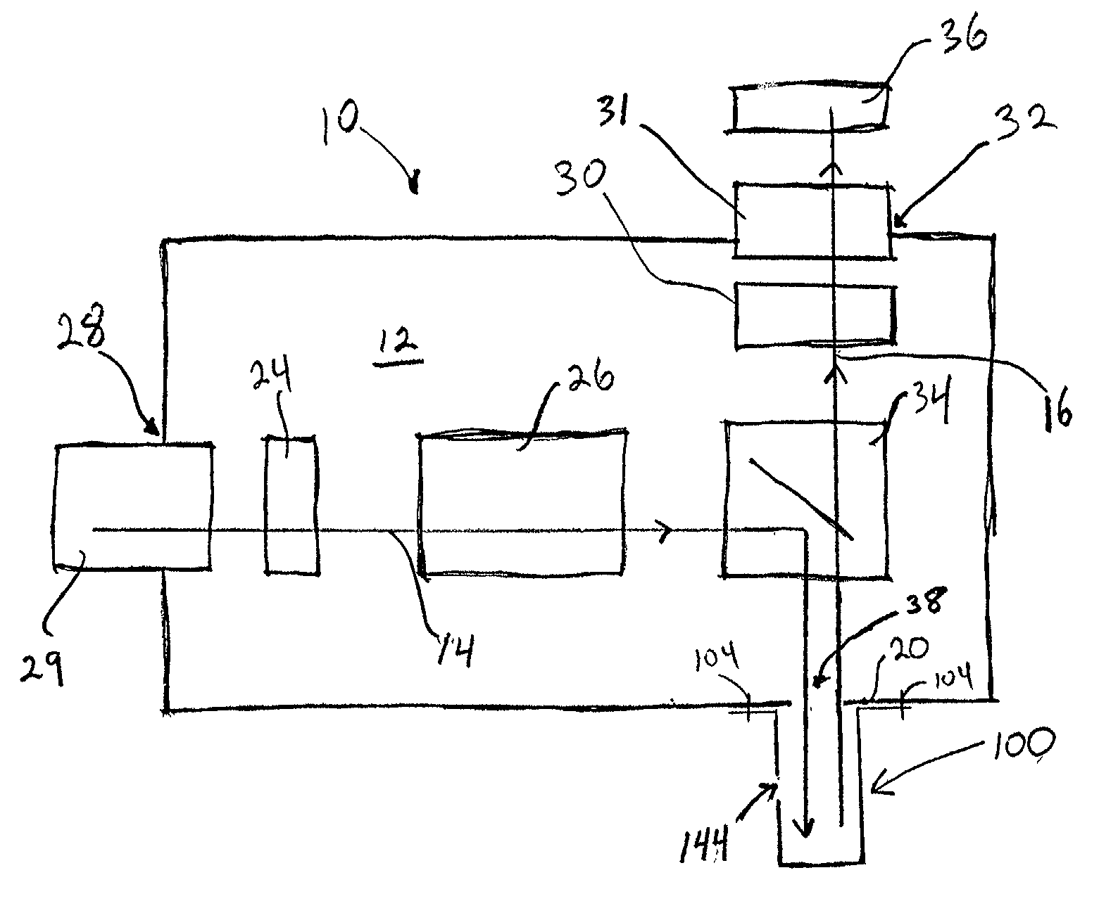
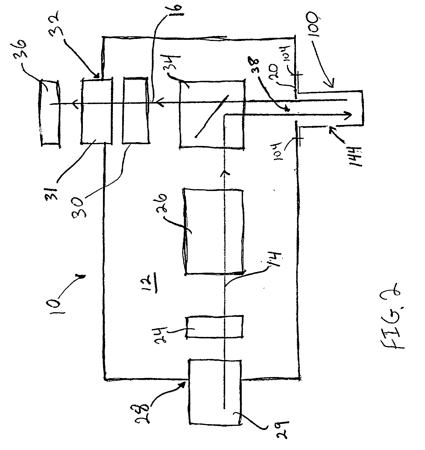
[0017] With reference to the drawings and, in particular, to FIGS. 2 and 3, a fixture 100 is provided that is releasably attachable to a microscope 10. The fixture 100 has a base or coupling end 102 which is configured for detachable alignment about the microscope objective lens port 38 on objective lens plane 20. The fixture 100 functions as an alignment reference tool to assist an assembler or technician of the microscope with the alignment of the various microscope optical components, including the objective lens, relative to a common alignment target positioned at a common reference location and allows for repositioning of the target within the fixture 100. The fixture permits the microscope optical components, including the objective lens, to be aligned with respect to a common reference location, thereby improving alignment accuracy and decreasing the alignment and set-up time of the optical microscope.

[0018] With continued reference to FIG. 3, the fixture base 102 is configur...


PUM


Abstract

A fixture and method is provided for aligning optical elements in a microscope. The fixture attaches to an objective lens plane of the microscope and supports an alignment optical element. During optical component alignment, an alignment beam is directed along the illumination and imaging paths of the microscope through the objective lens port and into the fixture for reflection by the alignment optical element. The fixture allows an alignment optical element positioned in a single location to be used for aligning the microscope components and for adjusting the microscope objective lens.

Description

[0001] 1. Field of the Invention[0002] This invention is directed to microscope optical component adjustment and, more particularly, to a device and method for assisting in the alignment of optical components in a microscope.[0003] 2. Description of the Related Art[0004] A prior art optical microscope 10 is shown in FIG. 1. The microscope contains a housing 12 which defines two optical paths; an illumination path 14 and an imaging path16. The illumination path provides light to an objective lens 18 proximate a sample plane 22 containing a sample (not shown), and the imaging path 16 directs the image of the sample obtained by the objective lens 18 to an output port 32 containing, for example, an eyepiece, camera, or other capturing device 36. Disposed along the illumination path 14 are illumination components such as a set of lenses 24 and a set of apertures 26, and the imaging path 16 also contains a set of apertures 30 and a set of lenses 31. As shown, both paths converge on, or ov...

Claims


Application Information

Patent Timeline
Patent Type & Authority Applications(United States)
IPC IPC(8): G02B21/24
CPCG02B21/24
Inventor SULLIVAN, NEAL T.
Owner SOLURIS
Why Eureka
Try Eureka