Plasma display panel including barrier ribs and method for manufacturing barrier ribs

a technology of plasma display panel and barrier rib, which is applied in the manufacture of electric discharge tubes/lamps, electrodes, and electrode systems, etc., can solve the problems of low aperture ratio of pdp, not giving much thought to how picture contrast is affected, and exhausting in an efficient manner during manufactur

Inactive Publication Date: 2004-01-01
SAMSUNG SDI CO LTD
View PDF5 Cites 39 Cited by
  • Summary
  • Abstract
  • Description
  • Claims
  • Application Information

AI Technical Summary

Problems solved by technology

A drawback of such a structure, however, is that a low aperture ratio of the PDP results.
However, the barrier ribs for separating the discharge cells of the pixels have been designed without giving much thought to how picture contrast is affected

Method used


Image

  • Plasma display panel including barrier ribs and method for manufacturing barrier ribs
  • Plasma display panel including barrier ribs and method for manufacturing barrier ribs
  • Plasma display panel including barrier ribs and method for manufacturing barrier ribs

Examples


Embodiment Construction

[0028] Exemplary embodiments of the present invention will now be described in detail with reference to the accompanying drawings.

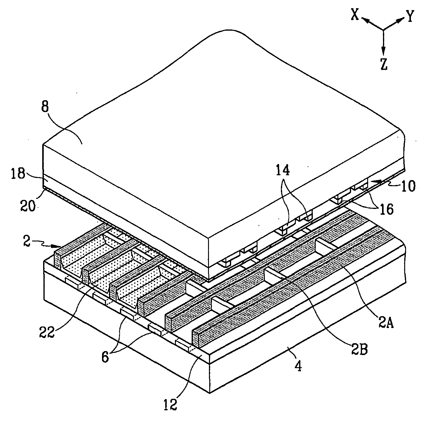
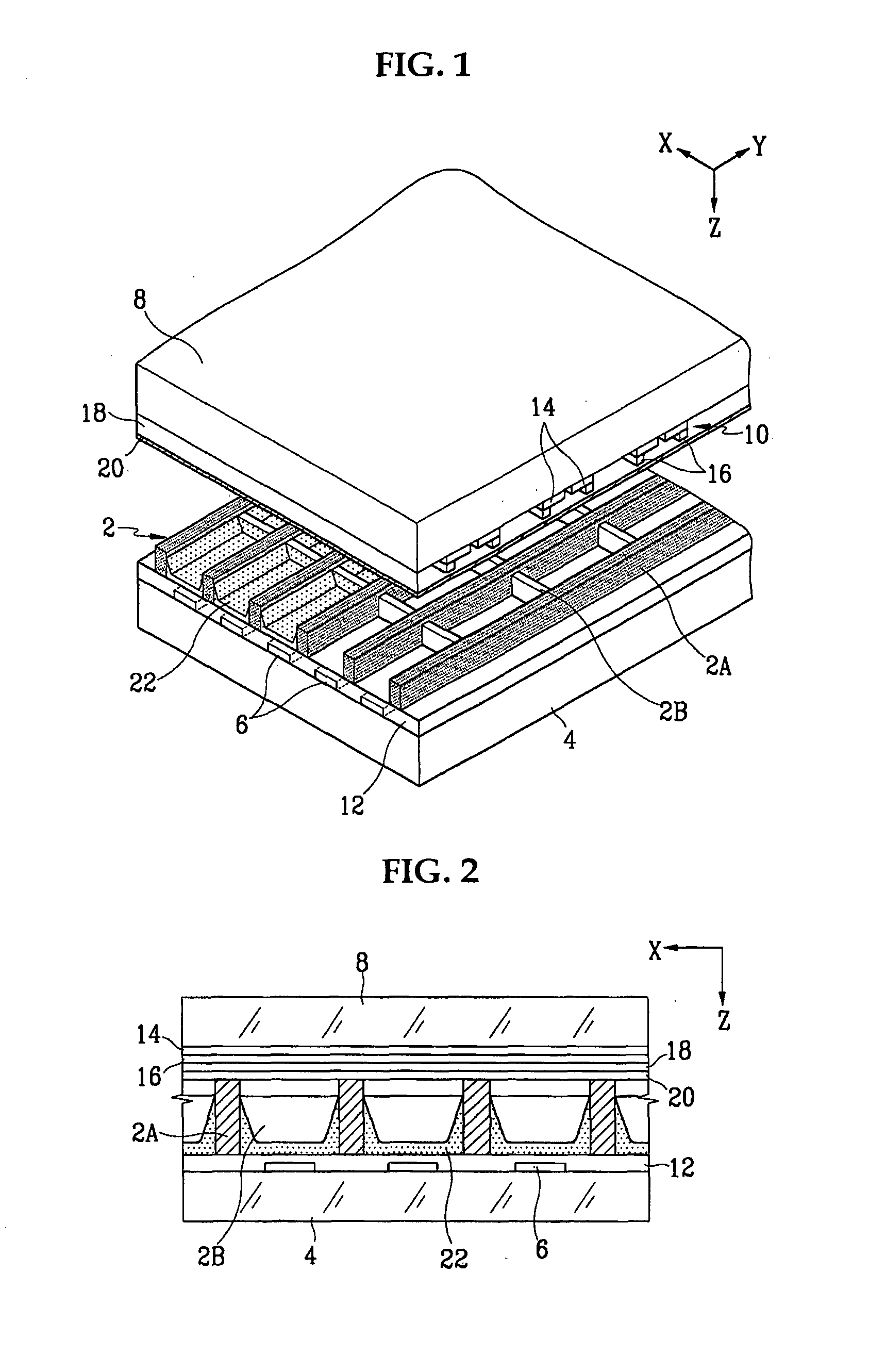
[0029] FIG. 1 is a partial exploded perspective view of a plasma display panel (PDP) according to a first exemplary embodiment of the present invention, and FIG. 2 is a sectional view showing the PDP of FIG. 1 in an assembled state and cut along an X-axis direction.

[0030] As shown in the drawings, corresponding portions of the barrier ribs 2 surround, in a "wall-like" manner, a plurality of R, G, and B pixels in a quadrilateral shape, for example, to define discharge cells. Corresponding to each of the pixels, address electrodes 6 are provided on a rear substrate 4 and discharge sustain electrodes 10 are provided on a front substrate 8. With this structure, illumination of the pixels and the intensity of illumination may be independently controlled.

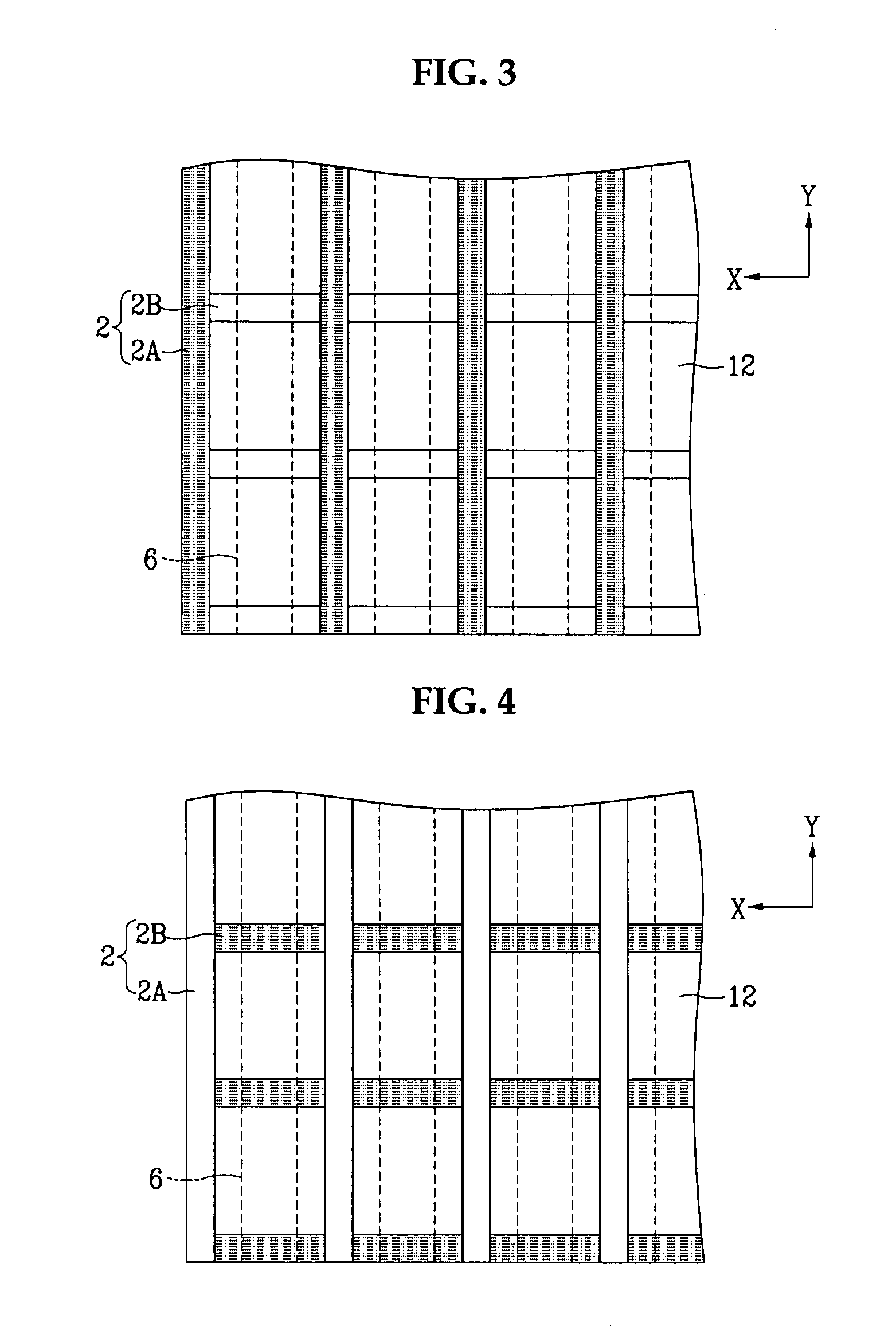
[0031] In more detail, a plurality of the address electrodes 6 are formed in a line pattern in Y-axis direct...


PUM


Abstract

The present invention provides a plasma display panel and a method for manufacturing barrier ribs for the plasma display panel. The plasma display panel includes first and second substrates that have a predetermined gap therebetween. A plurality of parallel address electrodes are formed on the first substrate. A dielectric layer is formed on the first substrate covering the address electrodes and barrier ribs are formed on the dielectric layer in a lattice pattern. Discharge sustain electrodes are formed on the second substrate which is perpendicular to the address electrodes, and a transparent dielectric layer and a protection layer are formed on the second substrate covering the discharge sustain electrodes. The barrier ribs are, for example, first and second barrier rib members which are formed respectively in the same direction as the address electrodes and the discharge sustain electrodes. Either or both the first barrier rib members or the second barrier rib members are made of a non-transparent material.

Description

[0001] This application is based on Korean Patent Application No. 2002-0036932 filed on Jun. 28, 2002. The content of the Application is fully incorporated by reference herein.[0002] 1. Field of the Invention[0003] The present invention relates to a method for manufacturing the barrier ribs and to a plasma display panel, and more particularly, to a plasma display panel in which substantially all of the red, green, and blue pixels are substantially surrounded by at least a portion of a plurality of barrier ribs.[0004] 2. Description of the Related Art[0005] A plasma display panel (PDP) is typically a display in which ultraviolet rays, which are generated by the discharge of gas, excite phosphors to realize predetermined images. As a result of the high resolution possible with PDPs, it is possible that PDPs will become one of the major next generation flat panel display configurations.[0006] In known PDPs, such as, the PDP shown in FIG. 13, address electrodes 3 are formed along a Y-ax...

Claims


Application Information

Patent Timeline
IPC IPC(8): H01J9/02H01J11/12H01J11/14H01J11/22H01J11/24H01J11/26H01J11/34H01J11/36H01J11/44
CPCH01J9/242H01J11/12H01J11/36H01J2211/444H01J2211/363H01J2211/366H01J11/44H01J9/24
Inventor MOON, CHEOL-HEE
Owner SAMSUNG SDI CO LTD
Why Eureka
Try Eureka