Three-dimensional shape measuring method, and three-dimensional shape measuring apparatus
a three-dimensional shape and measuring method technology, applied in the direction of measuring devices, instruments, using optical means, etc., can solve the problems of reducing the quantity of light, affecting the reliability of measurement results, and difficulty in adjusting the focus in every area of the object for measuremen
- Summary
- Abstract
- Description
- Claims
- Application Information
AI Technical Summary
Benefits of technology
Problems solved by technology
Method used
Image
Examples
first embodiment
[0033] First Embodiment
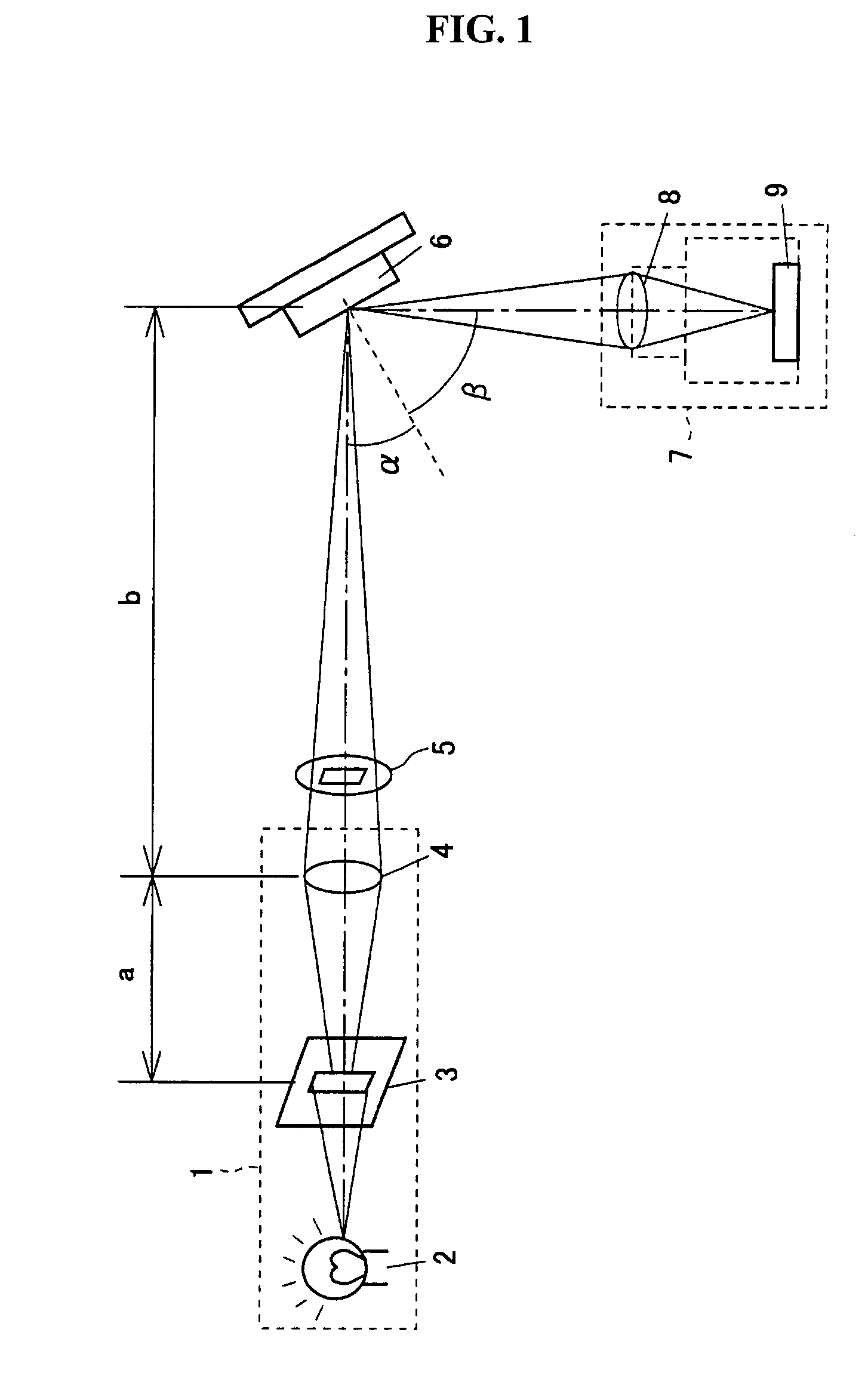
[0034] FIG. 1 is a schematic view of a three-dimensional shape measuring method and a three-dimensional shape measuring apparatus according to a first embodiment of the present invention. In the three-dimensional shape measuring apparatus, a projection optical system 1 is provided as shown in FIG. 1. The projection optical system 1 comprises a light source 2, a pattern forming unit 3 which is an optical slit, and a projection lens 4 which is, for example, a collective lens of the focal length f=48 mm.
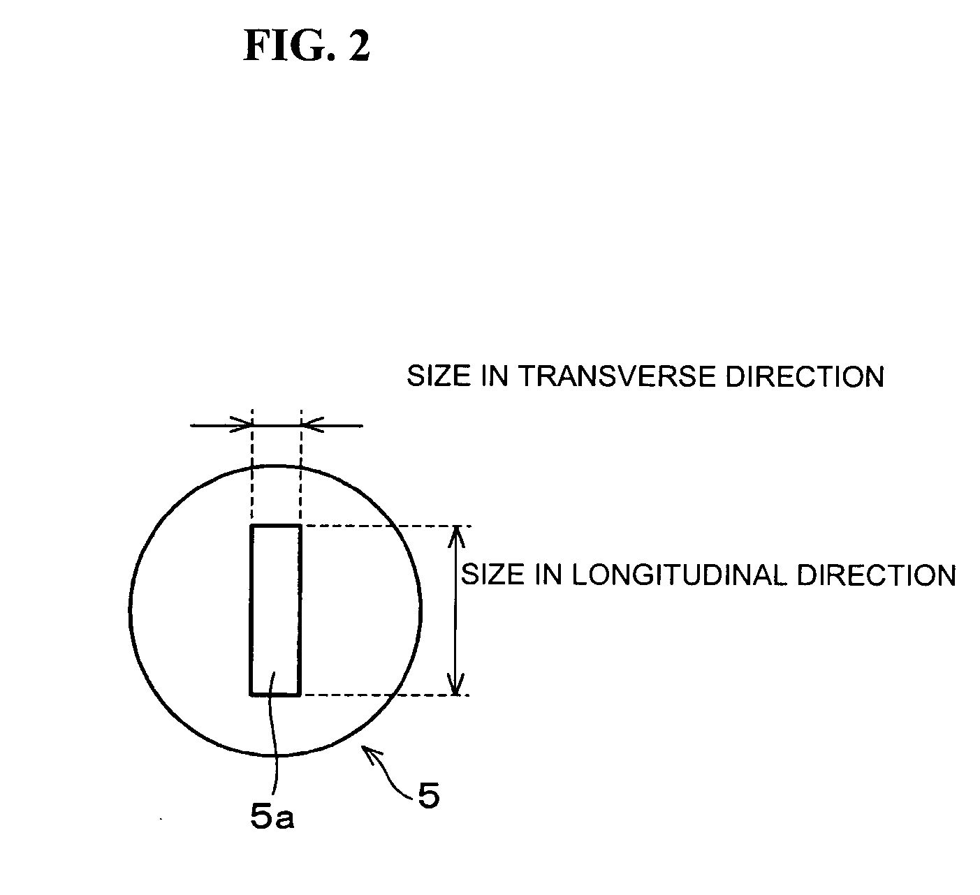
[0035] In addition, an asymmetric diaphragm (a diaphragm) 5 is provided between the projection lens 4 and an object 6 for measurement. This asymmetric diaphragm 5 has a rectangular aperture 5a (FIG. 2) in which the size in its transverse direction, which is perpendicular to the longitudinal direction of the slit of the pattern forming unit 3, is smaller than the size in the direction parallel to the slit direction as shown in FIG. 2. In other words, the asymmetric...
second embodiment
[0046] Second Embodiment
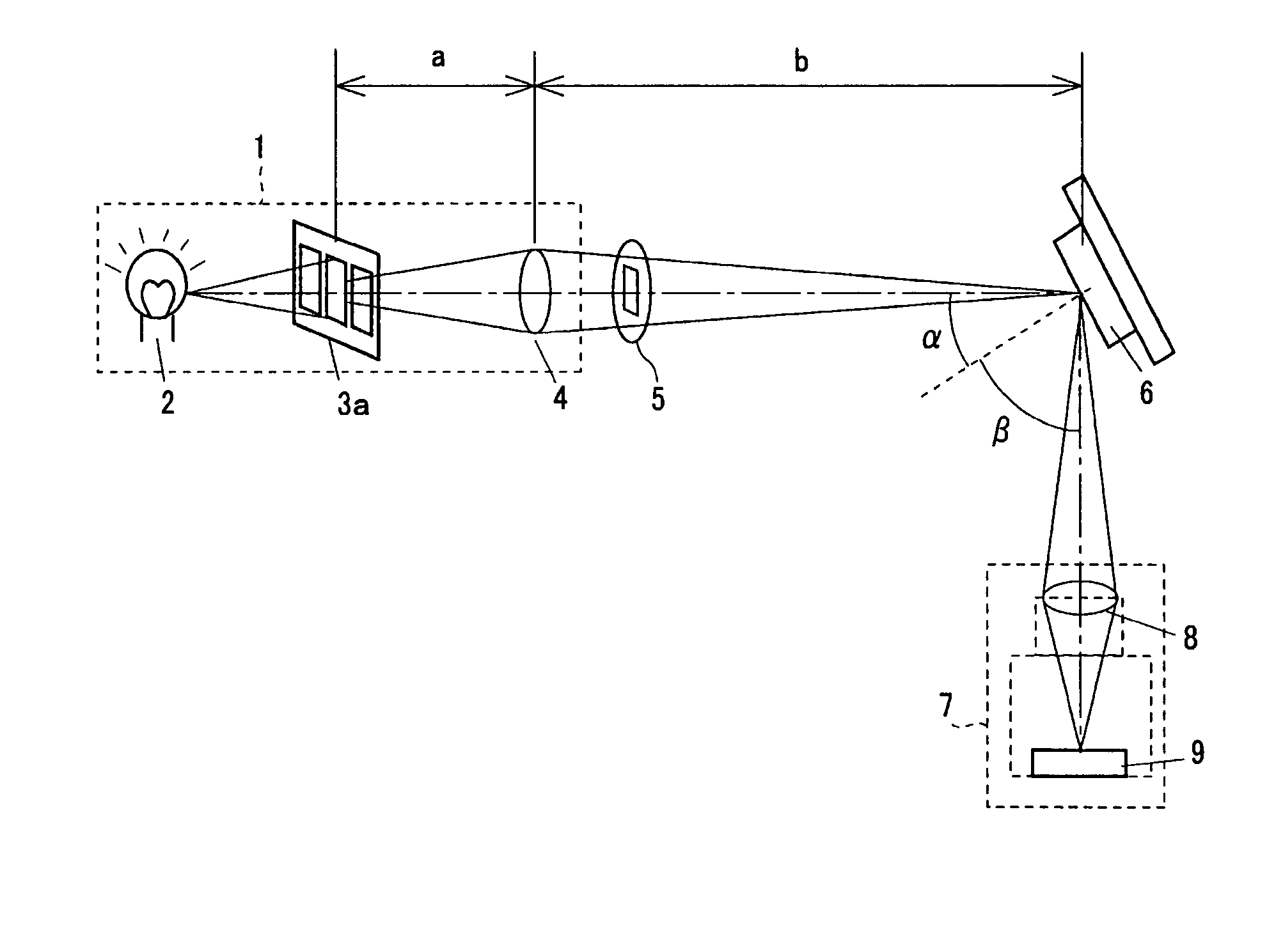
[0047] A three-dimensional shape measuring method and a three-dimensional shape measuring apparatus according to a second embodiment of the present invention will be described below. FIG. 6 is a schematic view of the three-dimensional shape measuring apparatus according to the second embodiment of the present invention. In the three-dimensional shape measuring apparatus, the light source 2, a pattern forming unit 3a of a plurality of slits, and the projection lens 4 are provided in the projection optical system 1 as shown in FIG. 6. In each embodiment described below, components according to the present embodiment which are identical to or correspond to those in the first embodiment are represented by the same reference numerals, and a detailed description thereof is omitted.
[0048] The pattern forming unit 3a is shown in FIG. 7. It comprises a light shielding unit 13 and a light shielding unit 14, and the light can be transmitted through only the light shield...
third embodiment
[0054] Third Embodiment
[0055] A three-dimensional shape measuring apparatus according to a third embodiment of the present invention will be described with reference to FIGS. 8 and 9.
[0056] As shown in FIG. 8, a mirror (a reflective optical system) 15 to reflect the reflected light is further provided on the three-dimensional shape measuring apparatus on the optical path between the object 6 and the image pickup optical system (detection unit) 7 so that the optical axis of the irradiated light from the projection optical system 1 is substantially parallel to the optical axis of the reflected light from the object 6 incident on the image pickup optical system (detection unit) 7.
[0057] By providing this mirror 15, the size of the entire measuring apparatus (in the longitudinal direction in FIG. 8, i.e., in the direction orthogonal to the optical axis of the light reaching the object 6 from the projection optical system 1) can be set to be small.
[0058] A modification of the three-dimen...
PUM
 Abstract
Description
Claims
Application Information
 - R&D
- Intellectual Property
- Life Sciences
- Materials
- Tech Scout
- Unparalleled Data Quality
- Higher Quality Content
- 60% Fewer Hallucinations
Browse by: Latest US Patents, China's latest patents, Technical Efficacy Thesaurus, Application Domain, Technology Topic, Popular Technical Reports.
© 2025 PatSnap. All rights reserved.Legal|Privacy policy|Modern Slavery Act Transparency Statement|Sitemap|About US| Contact US: help@patsnap.com


