Method of manufacturing electrolyzer unit, and method and system for welding electrolyzer unit and electrolyzer unit rib

a manufacturing method and electrolyzer technology, applied in the manufacture of tools, electrolysis components, welding/soldering/cutting articles, etc., can solve the problems of difficult to perform straining and cooling metal measures, and achieve the effect of suppressing the possibility of liquid leakage, reducing the number of welding portions, and prolonging the tim

Inactive Publication Date: 2004-01-15
FUJITA WORKS +1
View PDF14 Cites 11 Cited by
  • Summary
  • Abstract
  • Description
  • Claims
  • Application Information

AI Technical Summary

Benefits of technology

0201] All the frame members 32 do not have to be loaded after the insertion of the reinforcement members 47 is completed as described above. For example, some frame members 32 may be loaded beforehand and, after the reinforcement members 47 are inserted from the top side or bottom side, the remaining frame members 32 may be loaded.
0202] The bottom frame member 32b is supported in the direction of the top frame member 32a by the tension rods 48. Accordingly, when a liquid to be processed is supplied into the cathode chamber 18 and the anode chamber 14 during the operation of the analyzer to cause a downward load due to its weight, it is possible to effectively prevent the bottom frame member 32b from being curvedly deformed.
0203] A conventional structure is such that the lower end portions of the cathode ribs and anode ribs are TIG-welded to the inner wall surfaces of the cathode pan and anode pan to support the load by the cathode and anode ribs. This results in a very large number of welding portions, which in turn raises a serious risk of liquid leakage due to welding failures as well as the problem of the longer time it takes to manufacture the unit.
0204] In contrast, the use of the tension rods 48 eliminates the need for welding the rear end portions 16c of the cathode ribs and the rear end portions 12c of the anode ribs to the inner wall surface 15c of the cathode pan and the inner wall surface 11c of the anode pan, respectively, substantially reducing the number of welding portions and completely suppressing the possibility of liquid leakage due to welding failure.
0205] That is, as shown in FIG. 12, the tension rods 48 are inserted in the spaces in the electrolyzer unit 10 between the back surface 15b of the cathode pan and the back surface 11b of the anode pan 11, into which the liquid does not enter at all. Hence, even if there are faulty welds at the upper ends 48b or lower ends 48a of the tension rods 48, the electrolyzer unit is free from liquid leakage.

Problems solved by technology

However, even before the frame members are inserted, it is sufficiently possible to suppress thermal strains of the pan by taking such measures as "reverse straining" and "cooling metal" (if the first pan and the second pan are fixed together by inserting the frame members, the reserve straining and cooling metal measures become difficult to perform as the other pan interferes with the operation).

Method used


Image

  • Method of manufacturing electrolyzer unit, and method and system for welding electrolyzer unit and electrolyzer unit rib
  • Method of manufacturing electrolyzer unit, and method and system for welding electrolyzer unit and electrolyzer unit rib
  • Method of manufacturing electrolyzer unit, and method and system for welding electrolyzer unit and electrolyzer unit rib

Examples


example 2

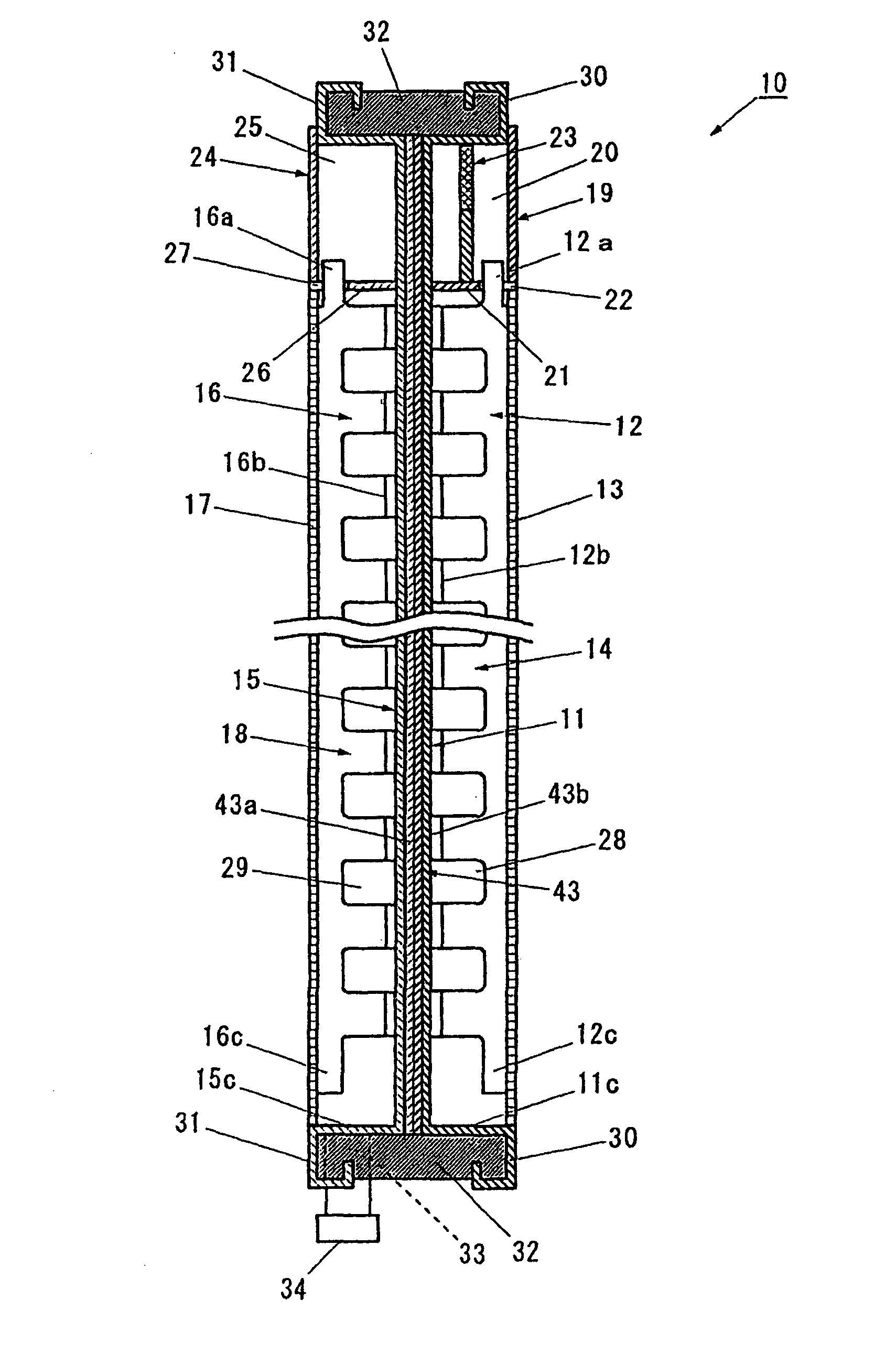
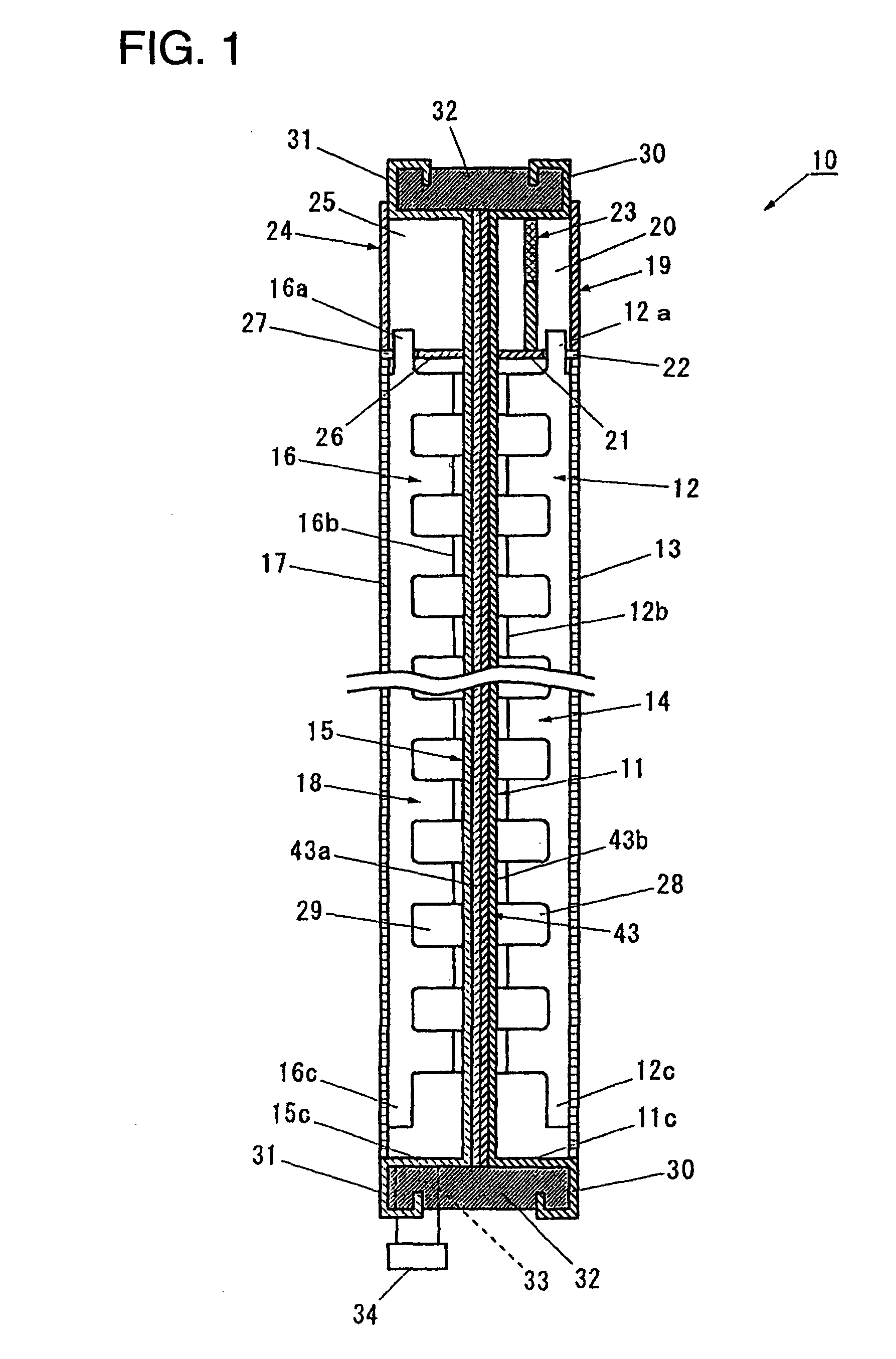
[0240] (1) Construction of Cathode Rib

[0241] Material.fwdarw.Nickel

[0242] Thickness.fwdarw.1.5 mm

[0243] Number of projections.fwdarw.One per pan contact portion

[0244] Height of projections.fwdarw.0.8 mm

[0245] Diameter of projections.fwdarw.7.0 mm

[0246] (2) Construction of Cathode Pan

[0247] Material.fwdarw.Nickel

[0248] Thickness.fwdarw.1.0 mm

[0249] (3) Construction of Clad Plate

[0250] Material.fwdarw.Stainless steel layer (SUS316)+titanium layer

[0251] Thickness of stainless steel layer.fwdarw.3.0 mm

[0252] Thickness of titanium layer.fwdarw.0.5 mm

[0253] (4) Construction of Anode Pan

[0254] Material.fwdarw.Titanium

[0255] Thickness.fwdarw.1.0 mm

[0256] (5) Construction of Anode Rib

[0257] Material.fwdarw.Titanium

[0258] Thickness.fwdarw.1.5 mm

[0259] Number of projections.fwdarw.One per pan contact portion

[0260] Height of projections.fwdarw.0.3 mm

[0261] Diameter of projections.fwdarw.7.0 mm

[0262] (6) Welding Condition

[0263] Weld voltage.fwdarw.400 V

[0264] Pressing force.fwdarw.440 kg

[0265] T...

example 3

[0268] (1) Construction of Cathode Rib

[0269] Material.fwdarw.Nickel

[0270] Thickness.fwdarw.1.5 mm

[0271] Number of projections.fwdarw.One per pan contact portion

[0272] Height of projections.fwdarw.0.8 mm

[0273] Diameter of projections.fwdarw.7.0 mm

[0274] (2) Construction of Cathode Pan

[0275] Material.fwdarw.Nickel

[0276] Thickness.fwdarw.1.0 mm

[0277] (3) Construction of Clad Plate

[0278] Material.fwdarw.Iron layer+titanium layer

[0279] Thickness of iron layer.fwdarw.3.3 mm

[0280] Thickness of titanium layer.fwdarw.0.7 mm

[0281] (4) Construction of Anode Pan

[0282] Material.fwdarw.Titanium

[0283] Thickness.fwdarw.1.0 mm

[0284] (5) Construction of Anode Rib

[0285] Material.fwdarw.Titanium

[0286] Thickness.fwdarw.1.5 mm

[0287] Number of projections.fwdarw.One per pan contact portion

[0288] Height of projections.fwdarw.0.3 mm

[0289] Diameter of projections.fwdarw.7.0 mm

[0290] (6) Welding Condition

[0291] Weld voltage.fwdarw.440 V

[0292] Pressing force.fwdarw.440 kg

[0293] Transformation ratio.fwdarw.30:1...


PUM

PropertyMeasurementUnit
depthaaaaaaaaaa
widthaaaaaaaaaa
widthaaaaaaaaaa

Abstract

The invention has an object of facilitating the detection of defective welds and improving the efficiency of manufacturing electrolyzer units. A a method of manufacturing an electrolyzer unit comprises a step of arranging a partition member on a front surface of a cathode pan and welding a top side and a left side of the cathode pan to the partition member to form a gas-liquid separation chamber, a step of performing a similar step on an anode pan, a step of arranging cathode ribs on a front surface of the cathode pan and clad plates on a back surface of the cathode pan at positions corresponding to the cathode ribs, welding them at the same time, putting a back surface of the anode pan over the back surface of the cathode pan and arranging anode ribs on a front surface of the anode pan at positions corresponding to the clad plates, a step of simultaneously performing on the anode pan a similar step of arranging anode ribs on a front surface of the anode pan at positions corresponding to the clad plates, and a step of inserting frame members into spaces formed between flange portions of the cathode pan and flange portions of the anode pan.

Description

[0001] The present invention relates to an electrolyzer unit that forms a bipolar electrolyzer for electrolyzing an alkaline metal chloride aqueous solution to produce chlorine and alkaline metal hydroxides.[0002] The invention also relates to a welding technique suited for manufacturing such an electrolyzer unit.[0003] Various types of bipolar electrolyzers for electrolyzing an alkaline metal chloride aqueous solution such as a salt solution through an ion exchange membrane method have been proposed, for example, in Japanese Patent Disclosure Nos. 51-43377, 58-71382, 62-96688, 5-9770, 9-95792, 10-158875 and 2000-26987.[0004] FIG. 25 is a cross sectional view showing a typical example of an electrolyzer unit which has been used in conventional bipolar electrolyzers.[0005] The conventional electrolyzer unit 100 has an anode chamber 104 constructed of an anode pan 101, anode ribs 102 arranged on a surface of the anode pan 101 and an anode 103 connected to end faces of the anode ribs 1...

Claims


Application Information

Patent Timeline
Patent Type & Authority Applications(United States)
IPC IPC(8): B23K11/00B23K11/14B23K11/20B23K11/26B23K31/00C25B1/16C25B1/26C25B9/17
CPCB23K11/002B23K11/14B23K11/26B23K2201/18Y10T29/5313C25B9/066C25B9/18Y10T29/53252C25B9/04B23K2101/18C25B9/65C25B9/19C25B9/70
Inventor FUJITA, KOJI
Owner FUJITA WORKS
Why Eureka
Try Eureka