Low-voltage high-speed frequency-divider circuit

Inactive Publication Date: 2004-01-22
THE HONG KONG UNIV OF SCI & TECH
View PDF3 Cites 19 Cited by
  • Summary
  • Abstract
  • Description
  • Claims
  • Application Information

AI Technical Summary

Problems solved by technology

The main problem with such conventional designs is that the minimum required supply voltage (V.sub.dd) is limited by the DC biasing requirements of the input gate terminals of the PMO

Method used


Image

  • Low-voltage high-speed frequency-divider circuit
  • Low-voltage high-speed frequency-divider circuit
  • Low-voltage high-speed frequency-divider circuit

Examples


Embodiment Construction

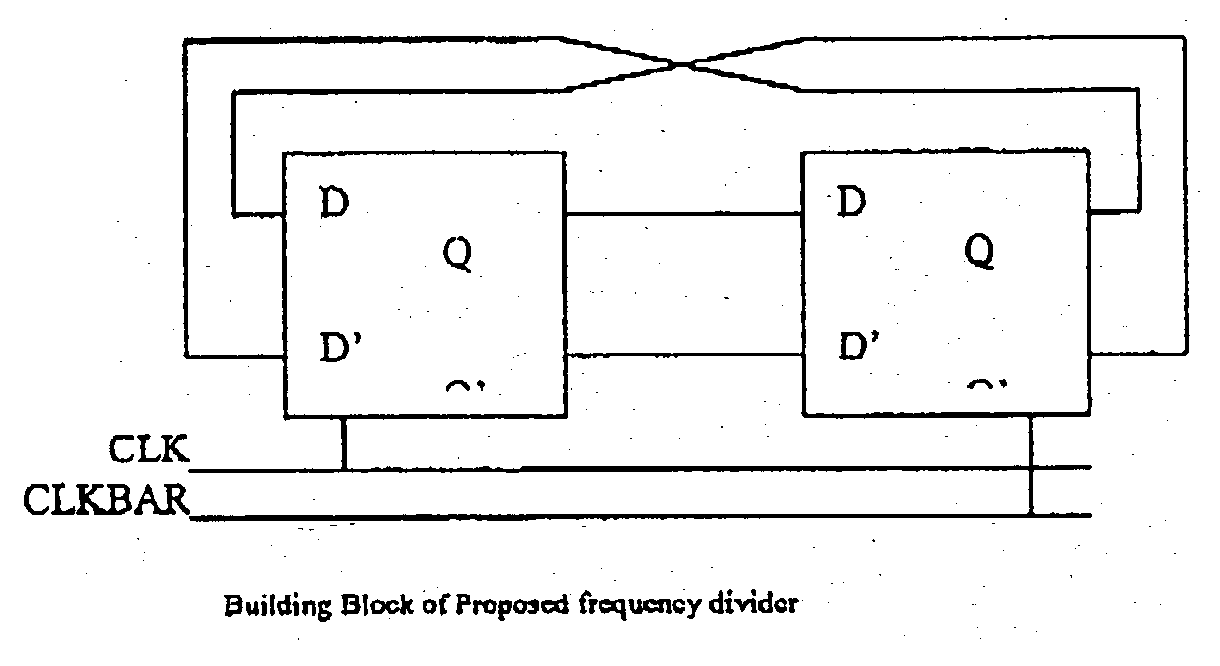
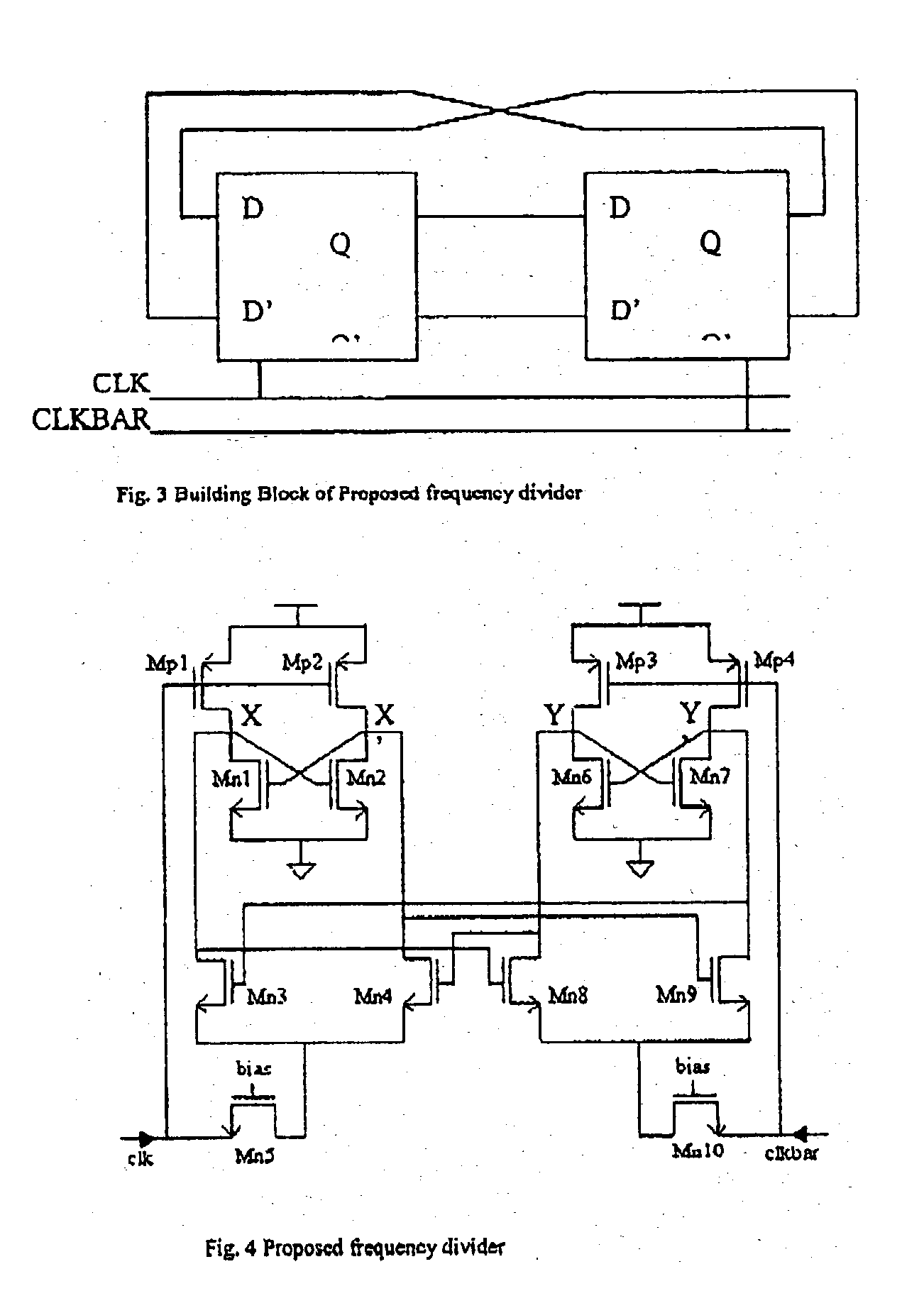
[0013] FIG. 3 shows the building blocks of an embodiment of the present invention and its schematic is shown in FIG. 4. The proposed frequency divider consists of two identical D-flip-flops cross-coupled with each other. Each circuit section generates an output signal driving the other, in other words the outputs of the first D-flip-flop are connected to the inputs of the second D-flip-flop, and similarly the outputs of the second D-flip-flop are fed back to the first D-flip-flop inputs. Unlike conventional frequency divider designs that employ a pair of complementary input signals within each D-flip-flop section, each of the D-flip-flops in the circuit of FIG. 3 is driven with a single input signal only. In this embodiment of the present invention, the first D-flip-flop is driven by an input signal (CLK), while the second D-flip-flop is driven by an input signal (CLKBAR), which is the complementary counterpart of CLK. The function of the two identical D-flip-flops is in a cooperati...


PUM


Abstract

A frequency divider circuit is disclosed that generates output signals having a frequency substantially half of the frequency of the input signal. The circuit comprises two D-Flip-Flop circuits wherein one employs the said input signal and the other one employs the complement of the said input signal, and each of the two D-Flip-Flop circuits consists of a pair of loading transistors, two regenerative pairs coupled with each others, and two common-gate switches.

Description

[0001] This invention relates a CMOS frequency divide-by-2 analog circuit, and in particular to a frequency divider that is capable of operation at very low supply voltages and very high frequencies.PRIOR ART[0002] Previous designs of Source-Coupled-Logic-Based frequency dividers employ two D-flip-flops in master / slave configuration as shown in FIG. 1. The output signal of one of the D-flip-flops is fed back to the input of the other D-flip-flop, and vice versa. Each D-flip-flop is controlled by a pair of complementary clock signals (CLK and CLKBAR). The function of the frequency divider is to receive a CLK signal having a frequency as one of the input and to produce an output signal equal to substantially half of the CLK frequency.[0003] A conventional high-speed frequency divider circuit is shown in FIG. 2. This circuit includes two identical D-flip-flop circuit sections. Each D-flip-flop needs a pair of complementary clock signals (CLK and CLKBAR) for proper operation. Each D-fli...

Claims


Application Information

Patent Timeline
IPC IPC(8): H03K3/356H03K23/54
CPCH03K3/356139H03K23/542H03K3/356147
Inventor CHEUNG, SIN-LUENWONG, MAN-CHUNLUONG, HOWARD CAM
Owner THE HONG KONG UNIV OF SCI & TECH
Why Eureka
Try Eureka