
Color 3D image display

Inactive Publication Date: 2004-02-05
YOSHINO KAZUTORA +1
View PDF2 Cites 80 Cited by
  • Summary
  • Abstract
  • Description
  • Claims
  • Application Information

AI Technical Summary

Problems solved by technology

In the conventional way, it was difficult to display the 3 dimensional object or images in real time (run time) by viewed by the multiple users without special glasses in the space only by light.
But many people feel uncomfortable wearing such devices and some gets cyber sick easily.
The holograms are showing 3 dimensional images, but these images are difficult to be changed in real time (run time).
(Actuality, Felix, Act Research) The conventional method to project the 2 dimensional images to plurality of semitransparent plates to create 3 dimensional images are very expensive because multiple DMD, GLV costs a lot.
And therefore, it is not suitable for user to touch the 3 dimensional image created by this device.
Also, this by itself is almost impossible to show the image in the space only by light.
But this device by itself would be unsuitable to show the real time (run time) 3 dimensional image because it is composed of two dishes.
Users can see from one angle and cannot locate themselves anywhere to look at the 3D image.
But in their method, it is not easy to make flat panel because it need extra-bright light source behind.
Also, it is difficult to apply current technology to manufactures.
It tends to be expensive.
Also, the data conversion from 3D object to 2D liquid crystal takes too long time to be for run time application.
And their resolution is low.

Method used


Image

  • Color 3D image display
  • Color 3D image display
  • Color 3D image display

Examples


Embodiment Construction

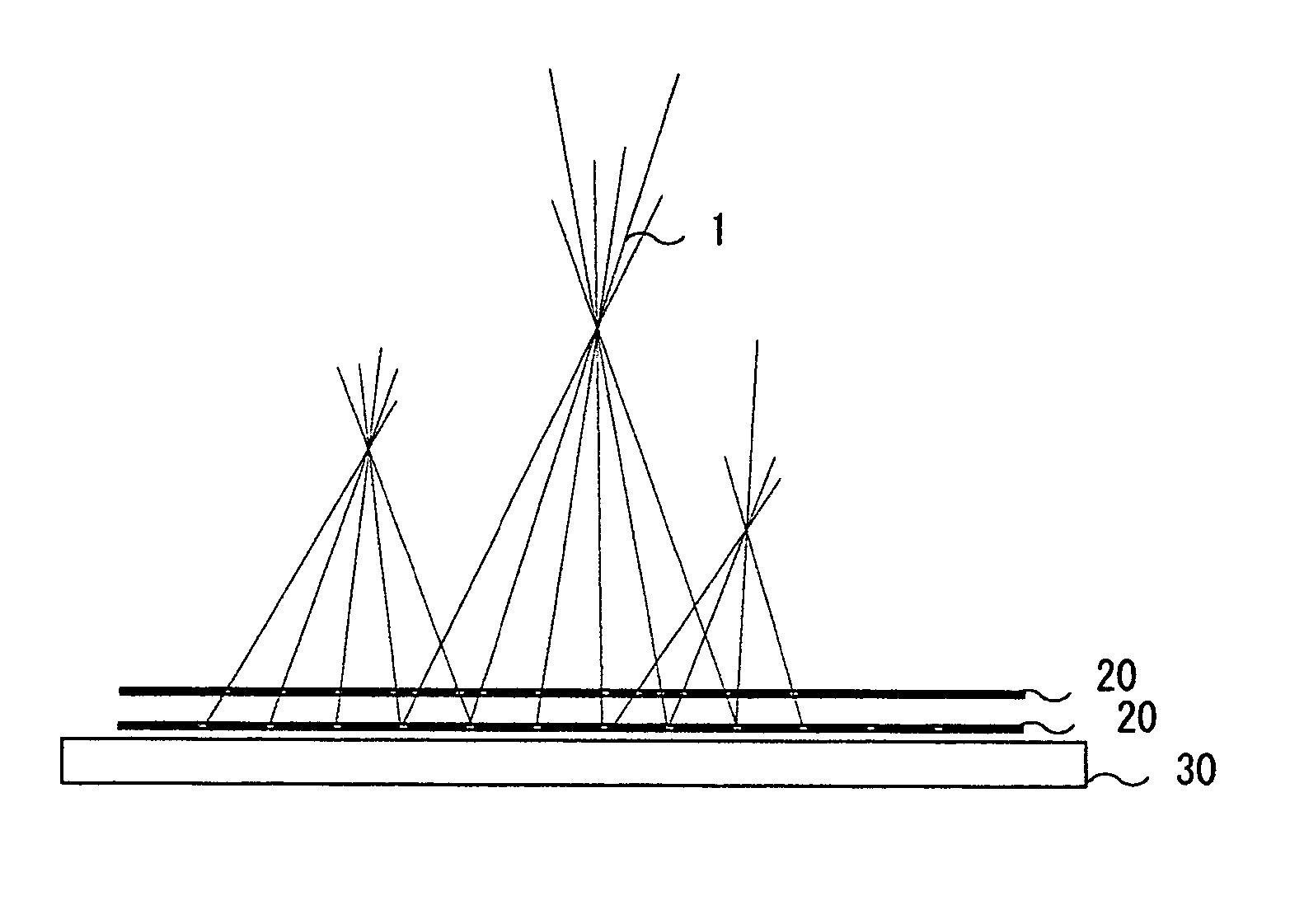
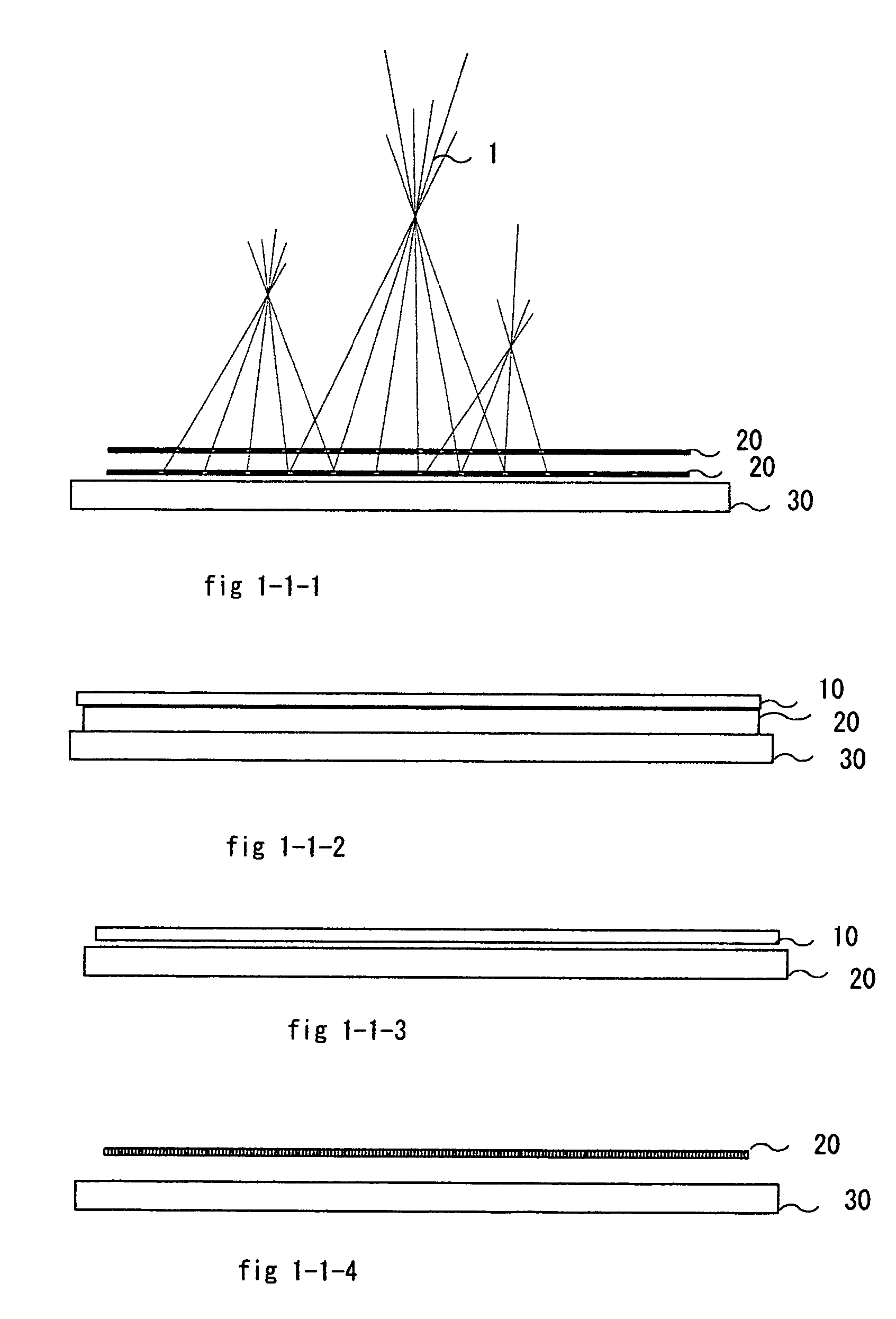
[0077] A preferred embodiment of intelligent system and the 3 dimensional Image Display inventions is illustrated in FIG. 1-1-1.

[0078] FIG. 1-1-1 shows the example diagrams of 3D display from side view. This can be made of fast response liquid crystal panels with polarizing plate (20) and light source (30). The first ferroelectric liquid crystal creates the patterns of pinholes arrays. The second liquid crystal creates the patterns with which 2D image would be converted to 3D image. By having different locations of pinholes in fast response shifting, it produces the high resolution of 3 dimensional images. The mask means can be inserted between those two panels.

Description--The Rest Alternative Embodiment

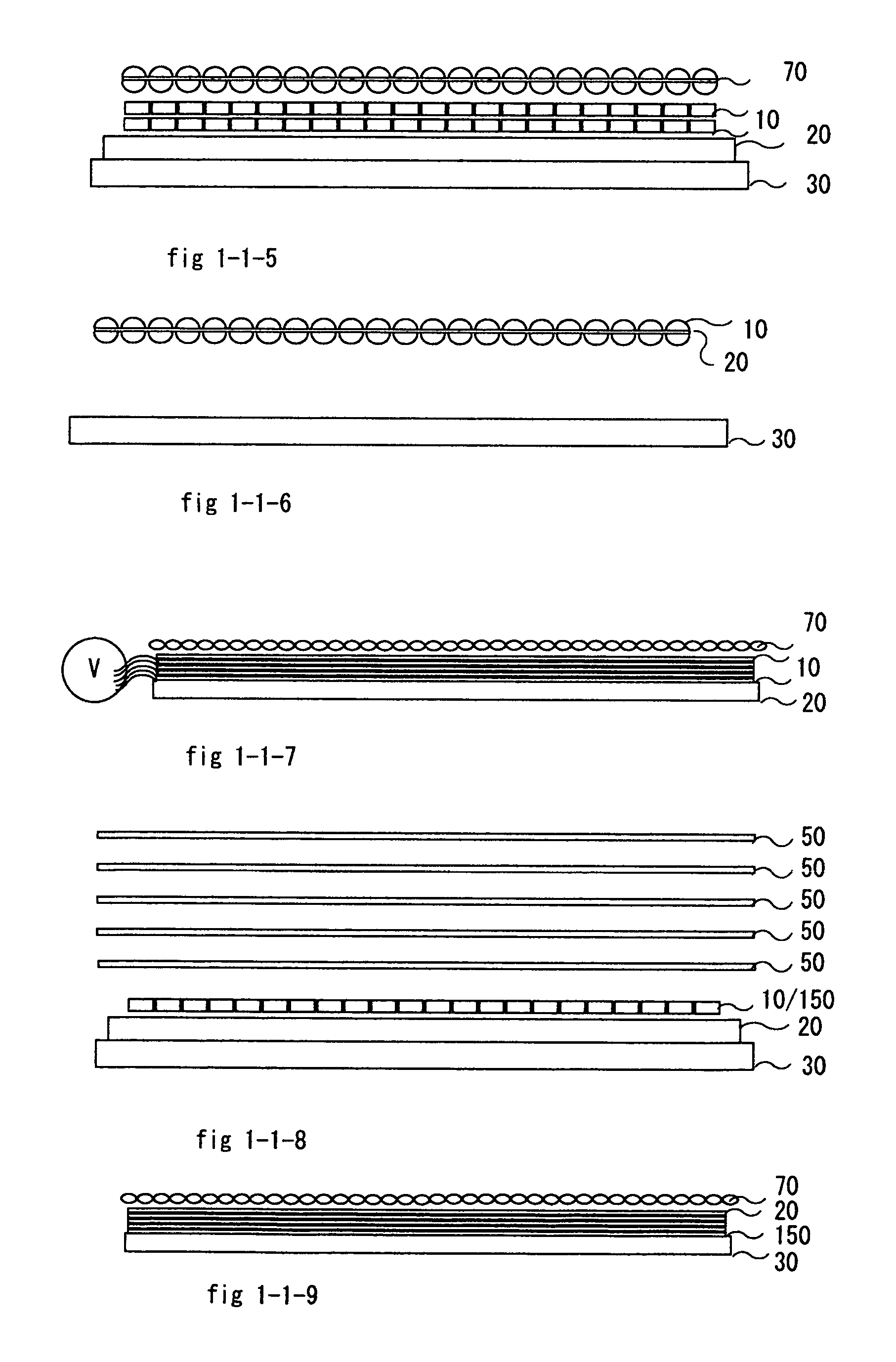
[0079] FIG. 1-1-2 shows the example diagrams of 3D display from side view. By having varifocal micro-lens arrays to 2D display such as liquid crystal panel with polarizing plate (20) and light source (3), it creates the 3D image.

[0080] FIG. 1-1-3 shows the example diagrams of 3D dis...


PUM

PropertyMeasurementUnit
Lengthaaaaaaaaaa
Diameteraaaaaaaaaa
Coloraaaaaaaaaa

Abstract

Color 3D image display devices that show realistic 3D images using the virtual light points fields. Color-intensity and directions of the virtual light points fields are controlled by various methods such as selection of directions of properly color-intensified light rays. For such methods, micro-pinholes, liquid crystal pinholes, varifocal micro-lens arrays and varifocal index-gradient lens, etc. are used together with high-resolution and high-speed 2 dimensional pattern-generating displays. By adding linear (reciprocating) and / or rotational motion to such 3D display makes higher resolution and view angles wider.

Description

FEDERALLY SPONSORED RESEARCH[0001] Not ApplicableSEQUENCE LISTING OR PROGRAM[0002] Not ApplicableBACKGROUND OF INVENTION[0003] 1. BACKGROUND--FIELD OF INVENTION[0004] This invention relates to the image display devices such as 3DTV, hologram, stereo display device, volumetric display device that are used for displaying the 3 dimensional object or images.[0005] 2. BACKGROUND--DESCRIPTION OF PRIOR ART[0006] In the conventional way, it was difficult to display the 3 dimensional object or images in real time (run time) by viewed by the multiple users without special glasses in the space only by light. So devices such as TV are showing the converted 2 dimensional images from the 3 dimensional objects.[0007] There are some 3 dimensional displays available.[0008] The virtual headsets are showing the two different images to each eye of users by screens to create the 3 dimensional images. The shutter glasses can also show 3D images having fast changing alternating left and right images. But ...

Claims


Application Information

Patent Timeline
IPC IPC(8): C08F4/642C08F110/02
CPCC08F4/642C08F110/02C08F4/025
Inventor YOSHINO, KAZUTORAYOSHINO, EMILY
Owner YOSHINO KAZUTORA
Learn More