
Devices and method for augmenting a vertebral disc

a technology of vertebral discs and devices, applied in the field of devices and methods for augmenting vertebral discs, can solve problems such as patient slipping

Inactive Publication Date: 2004-02-05
LAMBRECHT GREGORY +3
View PDF17 Cites 304 Cited by
  • Summary
  • Abstract
  • Description
  • Claims
  • Application Information

AI Technical Summary

Problems solved by technology

The most common resulting symptoms are pain radiating along a nerve and low back pain, both of which can be crippling for the patient.

Method used


Image

  • Devices and method for augmenting a vertebral disc
  • Devices and method for augmenting a vertebral disc
  • Devices and method for augmenting a vertebral disc

Examples


Embodiment Construction

[0055] Loss of vertebral disc tissue, such as NP, deflates the disc, causing a decrease in disc height. Significant decreases in disc height have been noted in up to 98% of operated patients. Loss of disc height increases loading on the facet joints, which may result in deterioration of facet cartilage and ultimately osteoarthritis and pain. As the joint space decreases, the neural foramina formed by the inferior and superior vertebral pedicles also close down which could lead to foraminal stenosis, pinching of the traversing nerve root, and recurring radicular pain. Loss of NP also increases loading on the remaining AF, and can produce pain. Finally, loss of NP results in greater bulging of the AF under load, which may result in renewed impingement by the AF on nerve structures posterior to the disc. Removal of NP may also be detrimental to the clinical outcome of disc repair.

[0056] Applicants own U.S. Pat. Nos. 6,425,919; 6,482,235; 6,508,839 and Published U.S. patent application ...


PUM

PropertyMeasurementUnit
compressive strengthaaaaaaaaaa
Poisson's ratioaaaaaaaaaa

Abstract

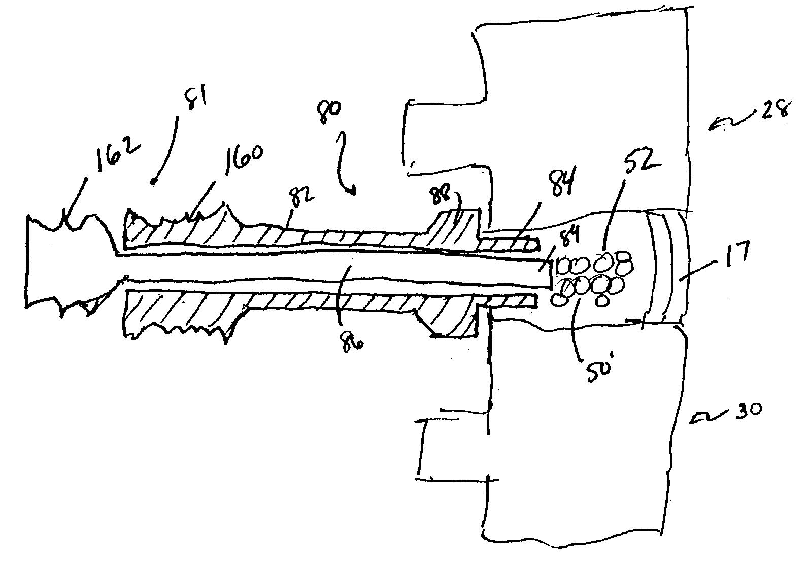
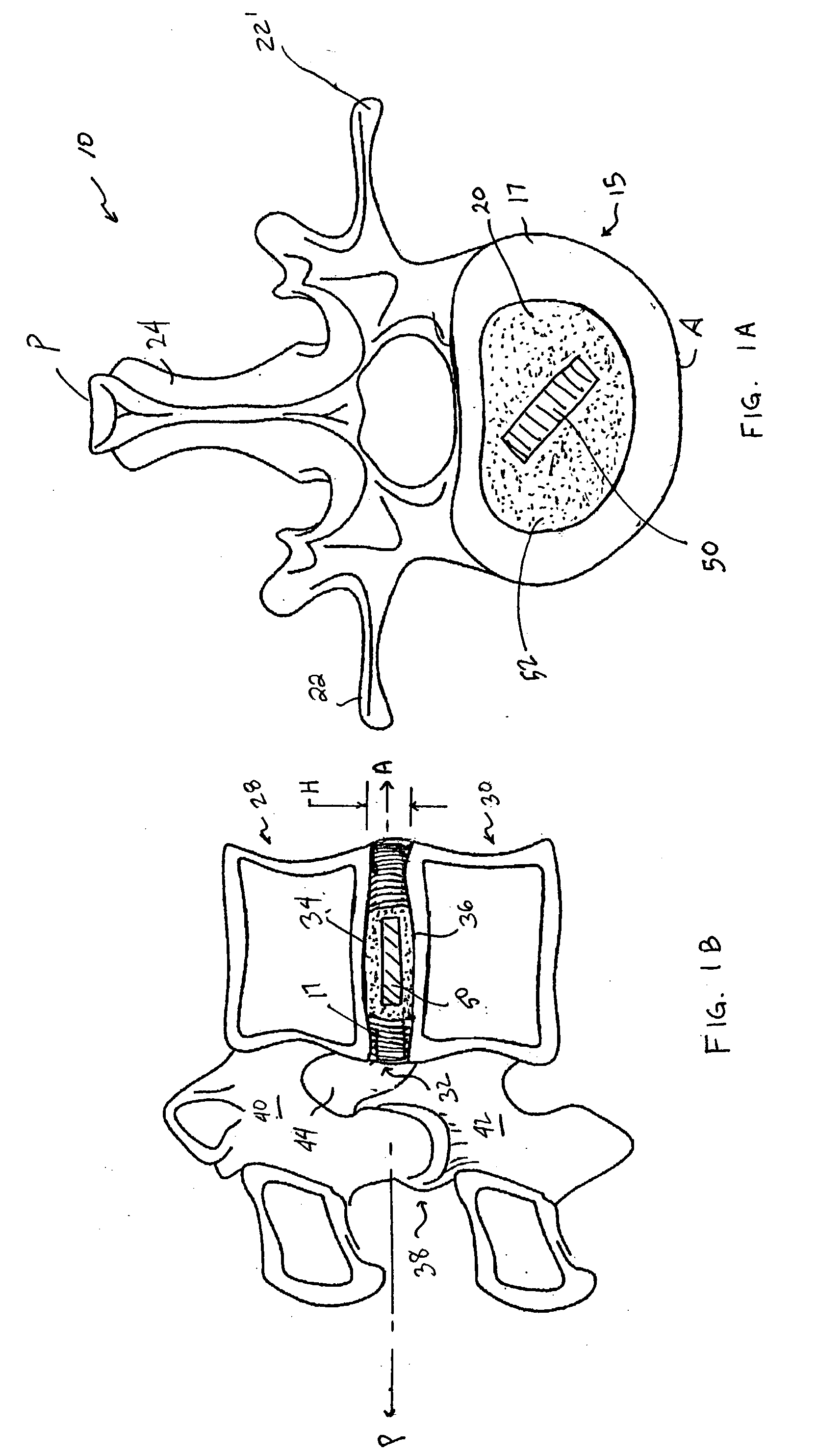
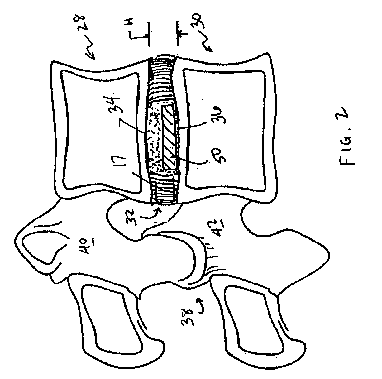
A vertebral disc prosthesis, a method of implanting a prosthesis and a deployment device is provided. The prosthesis may be implanted into the interior region of the vertebral disc so as to displace existing vertebral tissue, such as NP. The size or amount of the prosthesis inserted into the interior region of the vertebral disc may be a characteristic of the disc or the prosthesis. For example, the amount or size of prosthesis inserted into the disc may be dependent upon restoring the functionality of the disc (e.g., the ability of the disc to transfer nutrients or otherwise survive, the ability of the disc to carry the required loads and absorb stress or the reduction of pain). Restoring disc function may be determined by the resulting disc height desired, the resulting disc pressure desired or the resulting disc volume desired. The prosthesis may be sized or positioned within the interior of the vertebral disc such that it is spaced from at least one of the end plates of the vertebral disc. The prosthesis may be formed of a material having a compression strength that is less than 4 mn / m<2>. A deployment device may be used to facilitate placement of the prosthesis within the vertebral disc. The prosthesis may include a grouping of multiple components that can be deployed as group.

Description

[0001] This application claims the benefit of U.S. Provisional Application Ser. Nos. 60 / 439,261, filed on Jan. 10, 2003; 60 / 438,022, filed on Jan. 3, 2003; and 60 / 417,219, filed Oct. 9, 2002.[0002] This application is also a continuation-in-part of U.S. application Ser. No. 10 / 055,504 filed on Oct. 25, 2001, now pending, which is a continuation-in-part of U.S. application Ser. No. 09 / 696,636 filed on Oct. 25, 2000, now U.S. Pat. No. 6,508,839, which is a continuation-in-part of U.S. application Ser. No. 09 / 642,450 filed on Aug. 18, 2000, now U.S. Pat. No. 6,482,235, which is a continuation-in-part of U.S. application Ser. No. 09 / 608,797 filed on Jun. 30, 2000, now U.S. Pat. No. 6,425,919.[0003] Application Ser. No. 10 / 055,504 claims the benefit of U.S. Provisional Application Ser. No. 60 / 311,586 filed on Aug. 10, 2001. Application Ser. Nos. 09 / 642,450 and 09 / 608,797 each claim the benefit of U.S. Provisional Application Ser. Nos. 60 / 172,996, filed on Dec. 19, 1999; 60 / 161,085, filed...

Claims


Application Information

Patent Timeline
Patent Type & Authority Applications(United States)
IPC IPC(8): A61B5/107A61B17/00A61B17/22A61B17/32A61B17/34A61B17/70A61B19/00A61F2/00A61F2/02A61F2/28A61F2/30A61F2/44A61F2/46
CPCA61B5/1076A61B17/70A61B17/320016A61B17/320708A61B17/7095A61B2017/00261A61B2017/00557A61B2017/22077A61B2017/320044A61B2017/3445A61B2019/461A61B2019/462A61F2/2846A61F2/30723A61F2/30907A61F2/441A61F2/442A61F2/4601A61F2/4611A61F2/4657A61F2002/2817A61F2002/30062A61F2002/30075A61F2002/30131A61F2002/30224A61F2002/30228A61F2002/30291A61F2002/30462A61F2002/30571A61F2002/30583A61F2002/30589A61F2002/30677A61F2002/30777A61F2002/30785A61F2002/4435A61F2002/444A61F2002/448A61F2002/4627A61F2002/4635A61F2002/4658A61F2002/4661A61F2002/4662A61F2210/0004A61F2210/0061A61F2210/0085A61F2220/0075A61F2230/0013A61F2230/0069A61F2230/0091A61F2310/00017A61F2310/00023A61F2310/00029A61F2310/00293A61F2310/00365A61F2310/0097A61F2310/00976A61B17/7061A61B5/4514A61B2090/061A61B2090/062
Inventor LAMBRECHT, GREGORYPARTIN, JASONKAVANAUGH, SEANEINHORN, JACOB
Owner LAMBRECHT GREGORY
Learn More