

Method for cutting an object and or futher processing the cut material an carrier for holding the object and the cut material
- Summary
- Abstract
- Description
- Claims
- Application Information
AI Technical Summary
Benefits of technology
Problems solved by technology
Method used
Image

Examples
Embodiment Construction
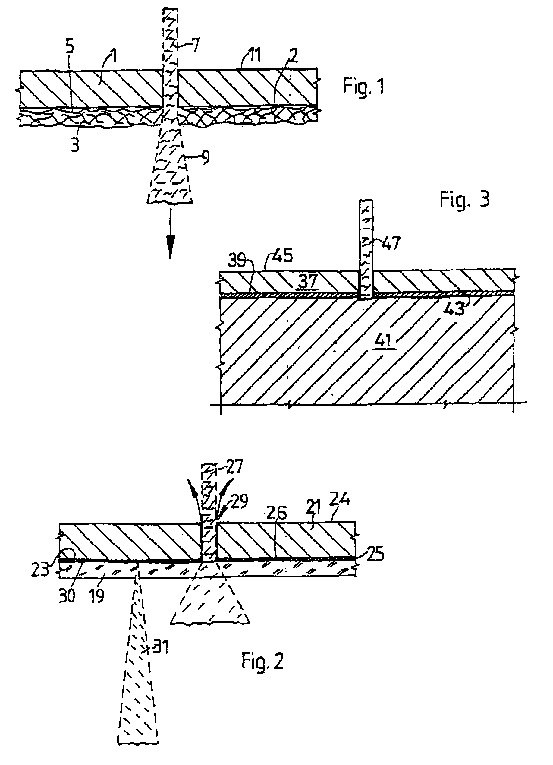
[0042] In the following text, examples of the carrier according to the invention and of the laser water-jet cutting according to the invention will be explained in more detail using several examples and with reference to the drawings, in which:
[0043] FIG. 1 shows a cross section through a mat-like carrier with an object adhesively bonded on,
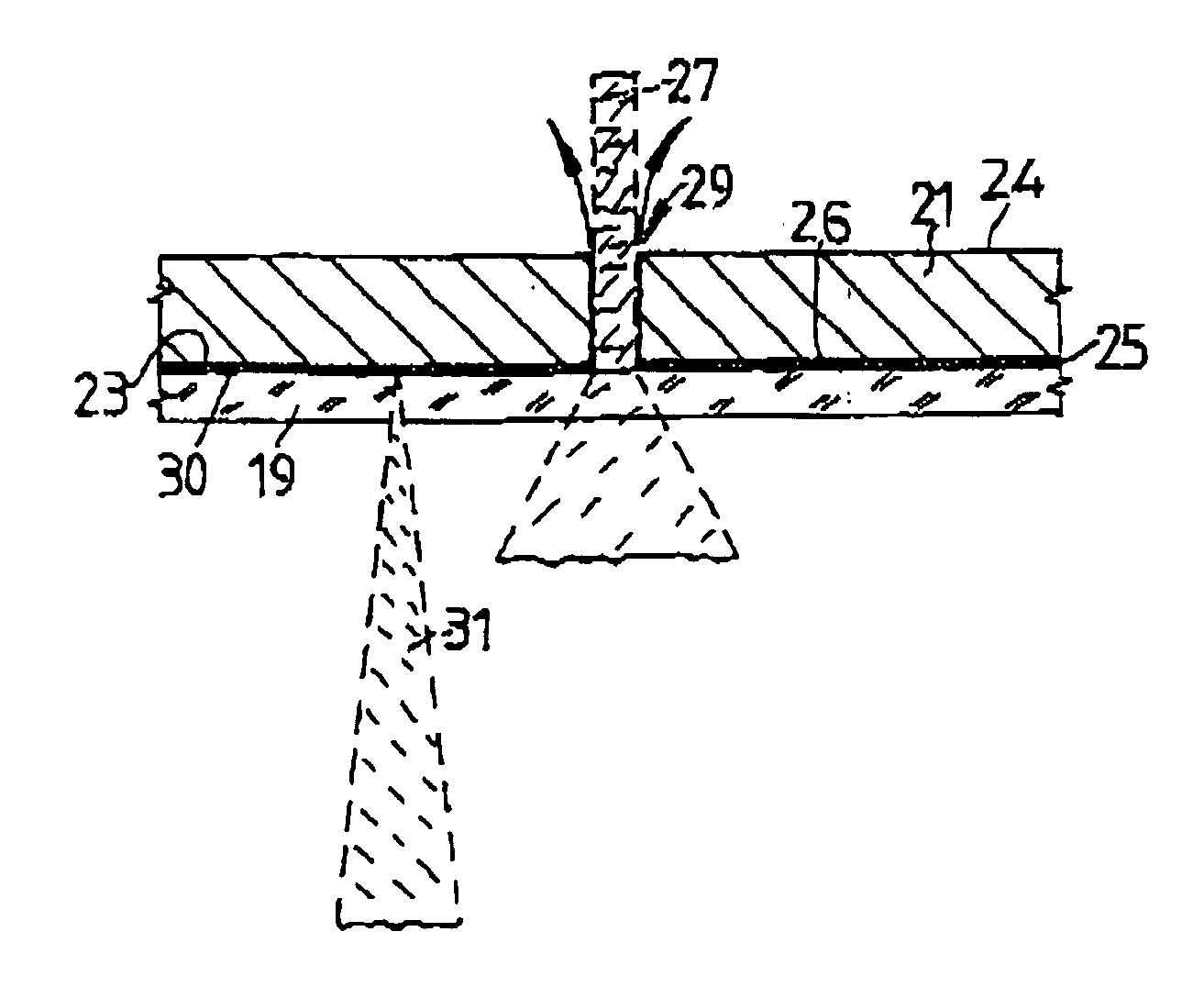
[0044] FIG. 2 shows, analogous to this, a cross section with a plate-like solid carrier and
[0045] FIG. 3 shows a variant of the method illustrated in FIGS. 1 and 2.
WAYS OF IMPLEMENTING THE INVENTION
[0046] FIG. 1 illustrates a silicon wafer 1 with its underside 2 adhesively bonded to a mat 3, in cross section. The "active" upper side 11 of the wafer 1 is free at the top. The mat 3 consists of fiber material covered or impregnated with adhesive. Since this is a fiber material, the surface 5 of the mat 3 is illustrated as irregular. However, it should be noted that this is a great exaggeration. This is because a laser water jet 7 cutting through the...
PUM
| Property | Measurement | Unit |
|---|---|---|
| Thickness | aaaaa | aaaaa |
| Transparency | aaaaa | aaaaa |
Abstract
Description
Claims
Application Information