Medium position sensing

a position sensing and medium technology, applied in the field of data storage, can solve problems such as limiting the range of focus and the field of view

Inactive Publication Date: 2004-02-12
AKONIA HOLOGRAPHICS
View PDF3 Cites 37 Cited by
  • Summary
  • Abstract
  • Description
  • Claims
  • Application Information

AI Technical Summary

Problems solved by technology

Furthermore, these applications are generally restricted to beams with relatively large numerical apertures (NA) and relatively small spot sizes (SS), thereby limiting the range of focus and the field of view.

Method used


Image

  • Medium position sensing
  • Medium position sensing
  • Medium position sensing

Examples


Embodiment Construction

[0036] 1. Two-Dimensional Push-Pull Position Sensing

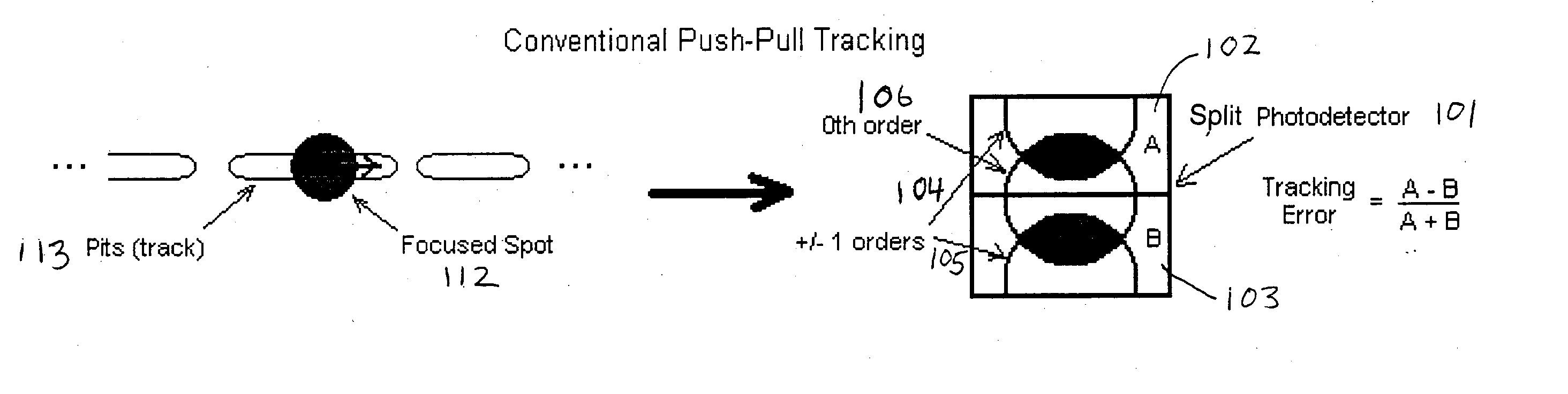
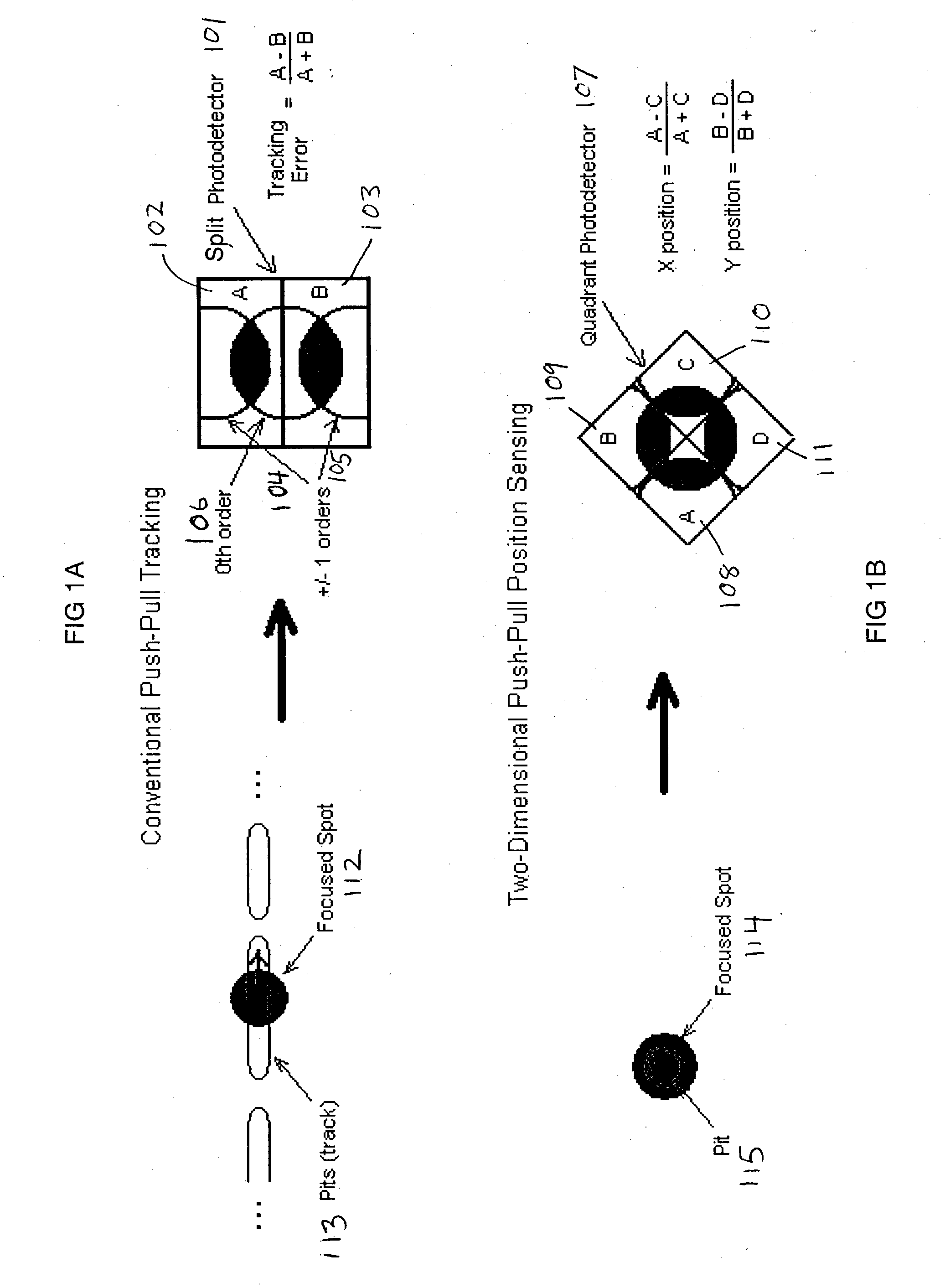
[0037] FIG. 1A illustrates conventional one-dimensional push-pull position sensing. A focused spot 112 from a beam is shown in relation to a track 113 (or configuration of pits). A split photodetector 101 with two segments (A 102 and B 103) provides a tracking error that results from the offset of the 1.sup.st-order components 104, 105, with respect to the 0.sup.th-order component 106 at the split photodetector 101. The outputs of A and B are current-based measurements that reflect the light intensity at the detector segments.

[0038] FIG. 1B illustrates two-dimensional push-pull position sensing as used in certain embodiments of the present invention. Similarly as in FIG. 1A, a focused spot 114 from a beam is shown in relation to a single pit 115. A quadrant photodetector 107 with four segments (A 108, B 109, C 110, and D 111) provides an analogous two-dimensional tracking error that results from the offset of the 1.sup.st-order com...


PUM

PropertyMeasurementUnit
widthaaaaaaaaaa
widthaaaaaaaaaa
widthaaaaaaaaaa

Abstract

A method of determining coordinates for a storage medium includes: determining diffraction data from a plurality of diffraction patterns corresponding to diffractive markers of the medium; and combining the diffraction data to determine composite coordinates for the medium. The composite coordinates may include three translational coordinates and three rotational coordinates. The act of determining diffraction data may include shining a plurality of beams on a selection of the diffractive markers, and measuring the corresponding diffraction patterns in one or more photodetectors to determine the diffraction data. In this latter case the photodetectors may be segmented. The act of combining the diffraction data to determine composite coordinates may include solving a matrix system that couples the diffraction data and the composite coordinates. Each diffractive marker may include a pit. The storage medium may include a holographic storage medium.

Description

[0001] This application claims the benefit of provisional application No. 60 / 352,099, filed Jan. 24, 2002, which is incorporated by reference in its entirety.[0002] 1. Field of Invention[0003] The present invention relates to data storage generally and more particularly to data storage in a holographic medium.[0004] 2. Description of Related Art[0005] Push-pull tracking (or sometimes "differential push-pull") is long established in the art of optical recording. For example, this approach has been used as a tracking-error sensing method for CDs (compact disks) and other optical disks. In this context, a coherent focused beam is reflected from the surface of the disk and detected in the far field. The interference pattern between the directly reflected beam (0.sup.th-order) and the components diffracted by the optical data tracks (.+-.1 orders) is detected by a split (two-element) photodetector to yield a highly sensitive tracking signal. ([1] Marchant, A. B., "Optical Recording: a te...

Claims


Application Information

Patent Timeline
Patent Type & Authority Applications(United States)
IPC IPC(8): G11B7/0065
CPCG11B7/0065G11B7/00781
Inventor AYRES, MARK R.LIPNEY, MICHAEL J.MALANG, KEITH W.GOODKNIGHT, CURT J.
Owner AKONIA HOLOGRAPHICS
Why Eureka
Try Eureka