
Method of manufacturing metal air cell system

a technology of metal air cell and air diffusion electrode, which is applied in the field of air diffusion electrode and cell system manufacturing, can solve the problems of not teaching the edge sealing of the gas electrode, the glued portion is prone to delamination after repeated use, and the electrolyte to leak at the junction of the cathode and the fram

Inactive Publication Date: 2004-02-19
EVIONYX INC
View PDF10 Cites 21 Cited by
  • Summary
  • Abstract
  • Description
  • Claims
  • Application Information

AI Technical Summary

Problems solved by technology

One of the principle obstacles of metal air electrochemical cells is the prevention of leakage of the electrolyte, typically a liquid electrolyte.
However, caustic electrolyte may destroy this seal, causing electrolyte to leak at the juncture of the cathode and the frame.
Further, this glued portion is prone to delaminating after repeated use, for example, in a cell that is designed to have the anode removed and replaced (e.g., in a refuelable configuration).
However, Solomon does not teach how to seal the edges of the gas electrode, a critical source of electrolyte leakage.
However, these are formed separately from the air diffusion electrodes, and no protection is provided at the edges thereof.
However, such methods are time consuming, in that the air diffusion manufacturing process must be modified to incorporate the edge coated regions.
However, the adhesion is subject to delaminating problems as described heretofore.
However, such methods may not be suitable for the metal air cells.
First, caustic resistant injection molding material (e.g., ABS plastic) is prone to shrinkage, which may lead to undesirable cell and / or electrode deformation.
Further, high pressures required with injection molding techniques, generally both in the form of clamping pressures to secure the mold, and injection pressures to inject the material.
Such pressures may adversely affect the components themselves and the arrangement of the loose parts (since many of the parts used are not secured during the molding process).
Additionally, injection molding techniques typically require temperatures of at least 200 degrees C., which will substantially detriment the electrodes and certain plastic frame components (e.g., the air frame).

Method used


Image

  • Method of manufacturing metal air cell system
  • Method of manufacturing metal air cell system
  • Method of manufacturing metal air cell system

Examples


Embodiment Construction

[0018] A metal air cell includes an anode and the cathode. An electrolyte is disposed between the cathode and the anode, the electrolyte provided within the anode, separately at the interface between the cathode and the anode, or both within the anode and separately at the interface between the cathode and the anode.

[0019] Referring now to the drawings, an illustrative embodiment of the present invention will be described. For clarity of the description, like features shown in the figures shall be indicated with like reference numerals and similar features as shown in alternative embodiments shall be indicated with similar reference numerals.

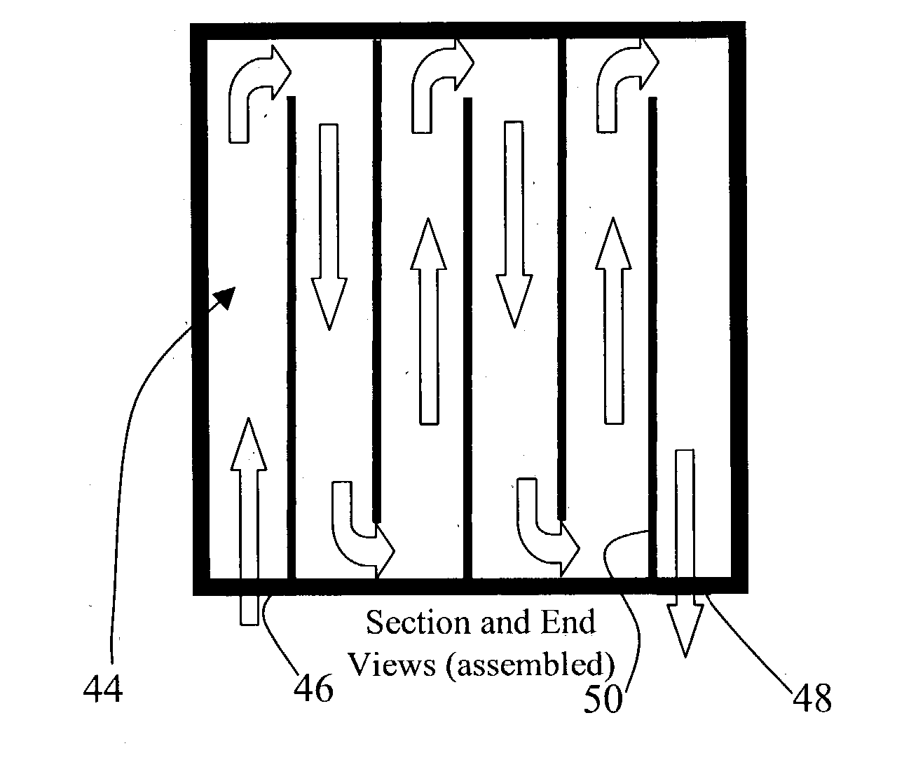
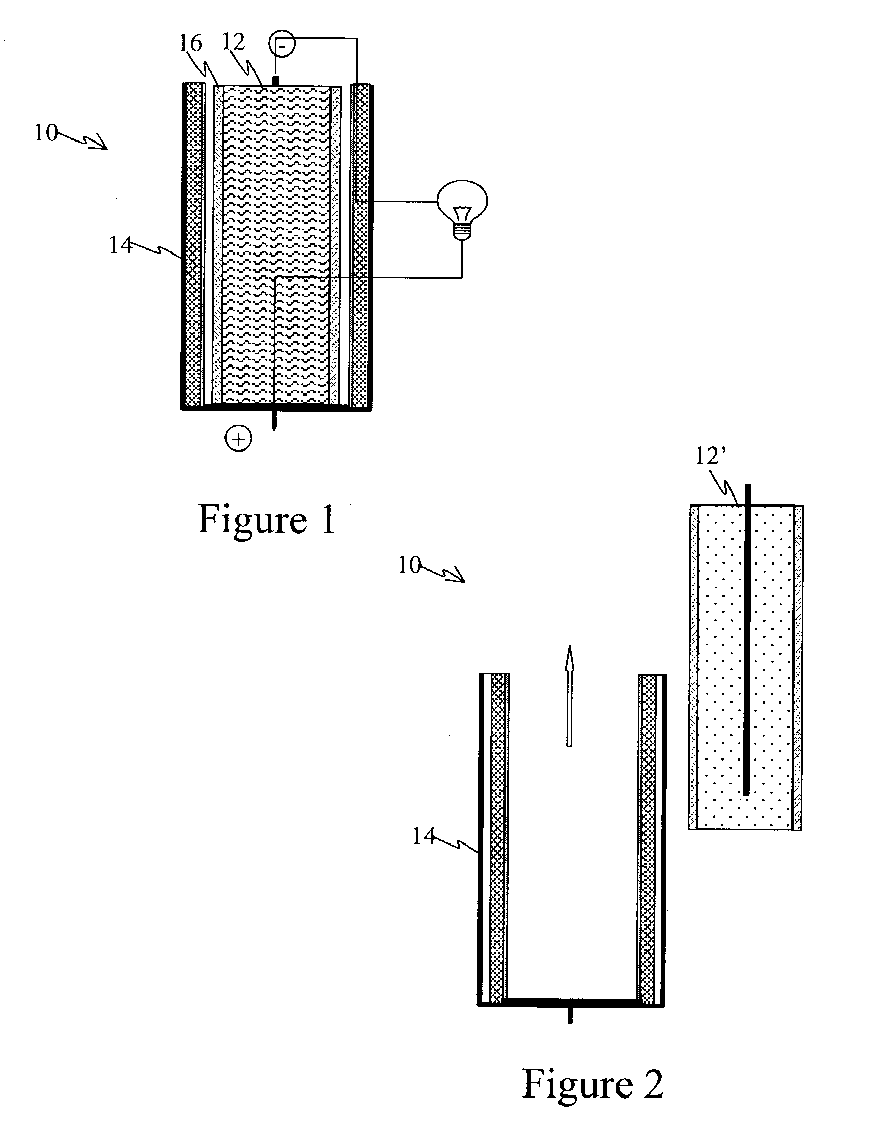
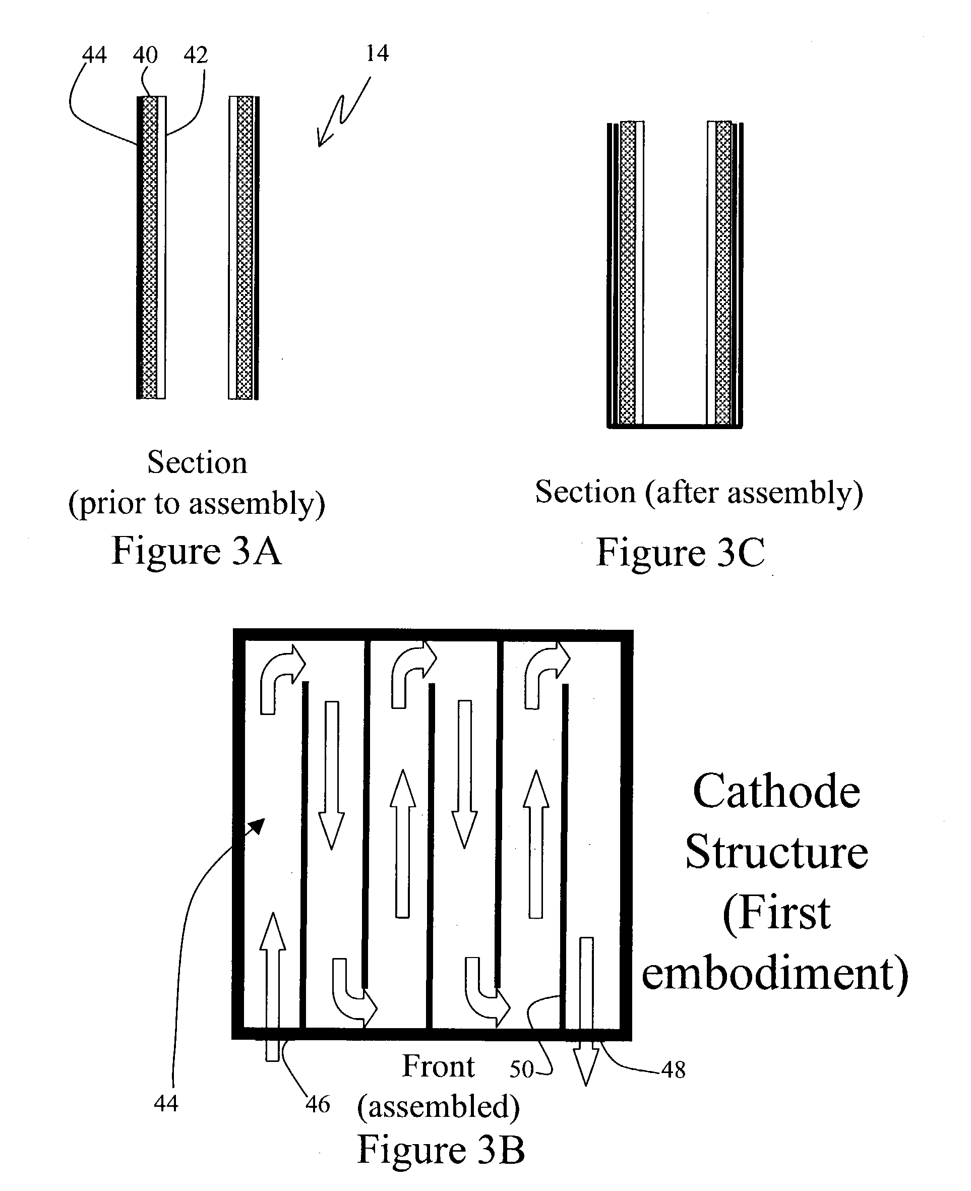
[0020] Referring now to FIG. 1, a metal air electrochemical cell 10 of a generally prismatic configuration is depicted. The cell 10 includes an anode structure 12 within an essentially U-shaped housing 14 holding a pair of active air diffusion electrode portions, and capable of holding a quantity of liquid electrolyte. The anode structure 12 and...


PUM

PropertyMeasurementUnit
Temperatureaaaaaaaaaa
Pressureaaaaaaaaaa

Abstract

The present invention provides a method of manufacturing metal air cell systems. The method includes a thermoset molding step to integrate the cell structure with necessary cell components. This method offers reliable, stable structure and, most importantly, good bonding with porous components (e.g., air cathode, charging cathode) to prevent potential leakage.

Description

[0001] The present invention claims priority to U.S. Provisional Patent Application No. 60 / 384,550 filed on May 31, 2002, which is incorporated by reference herein.[0002] 1. Field of the Invention[0003] This invention relates to air diffusion electrodes and cell systems using such electrodes, and particularly to a method of manufacturing air diffusion electrodes and metal air cell systems using air diffusion electrodes.[0004] 2. Description of the Prior Art[0005] Electrochemical power sources are devices through which electric energy can be produced by means of electrochemical reactions. These devices include metal air electrochemical cells such as zinc air, aluminum air and magnesium air batteries or fuel cells. Such cells generally use the metal as the negative electrode, and oxygen diffused through an air diffusion electrode as the positive electrode. The air diffusion electrode generally comprises a semipermeable membrane and a catalyzed layer for electrochemical reaction. An el...

Claims


Application Information

Patent Timeline
IPC IPC(8): B29B13/00B29C43/18H01MH01M12/08H01M50/103H01M50/186H01M50/193H01M50/489
CPCH01M2/0207H01M2/08Y10T29/49114H01M12/08H01M2/14Y02E60/10H01M50/186H01M50/103H01M50/193H01M50/489
Inventor MORRIS, WILLIAMTSAI, TSEPIN
Owner EVIONYX INC
Learn More