Information transmission over power lines

Inactive Publication Date: 2004-02-19
MAIN NET COMM
View PDF13 Cites 128 Cited by
  • Summary
  • Abstract
  • Description
  • Claims
  • Application Information

AI Technical Summary

Benefits of technology

0022] To mount the coupler to a line, the two parts of the coupler are separated or distanced from each other. The line is positioned between the parts and the two parts brought together so that after being brought together the line is located and held in the open space at the cent

Problems solved by technology

For high and medium voltage power line networks, such connections are generally undesirable.
Connecting a T/R to such power line by direct conductive contact is usually labor intensive and can often be dangerous.
However, the publication does not describe how this may be accomplished for high voltage power lines (contact with which is not allowed) and in particular for uninsulated high voltage power lines.
F

Method used


Image

  • Information transmission over power lines
  • Information transmission over power lines
  • Information transmission over power lines

Examples


Embodiment Construction

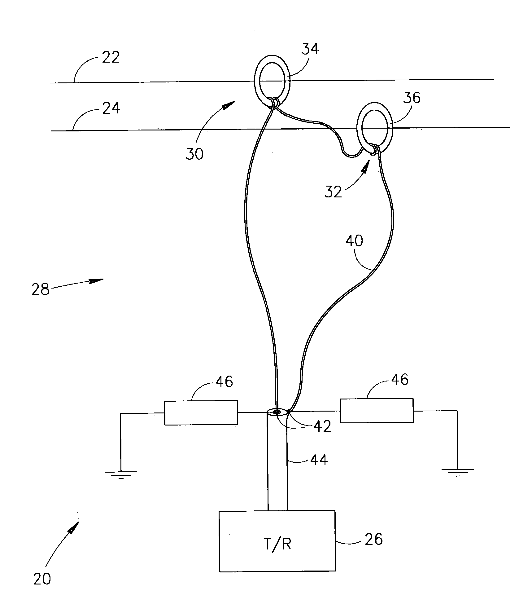
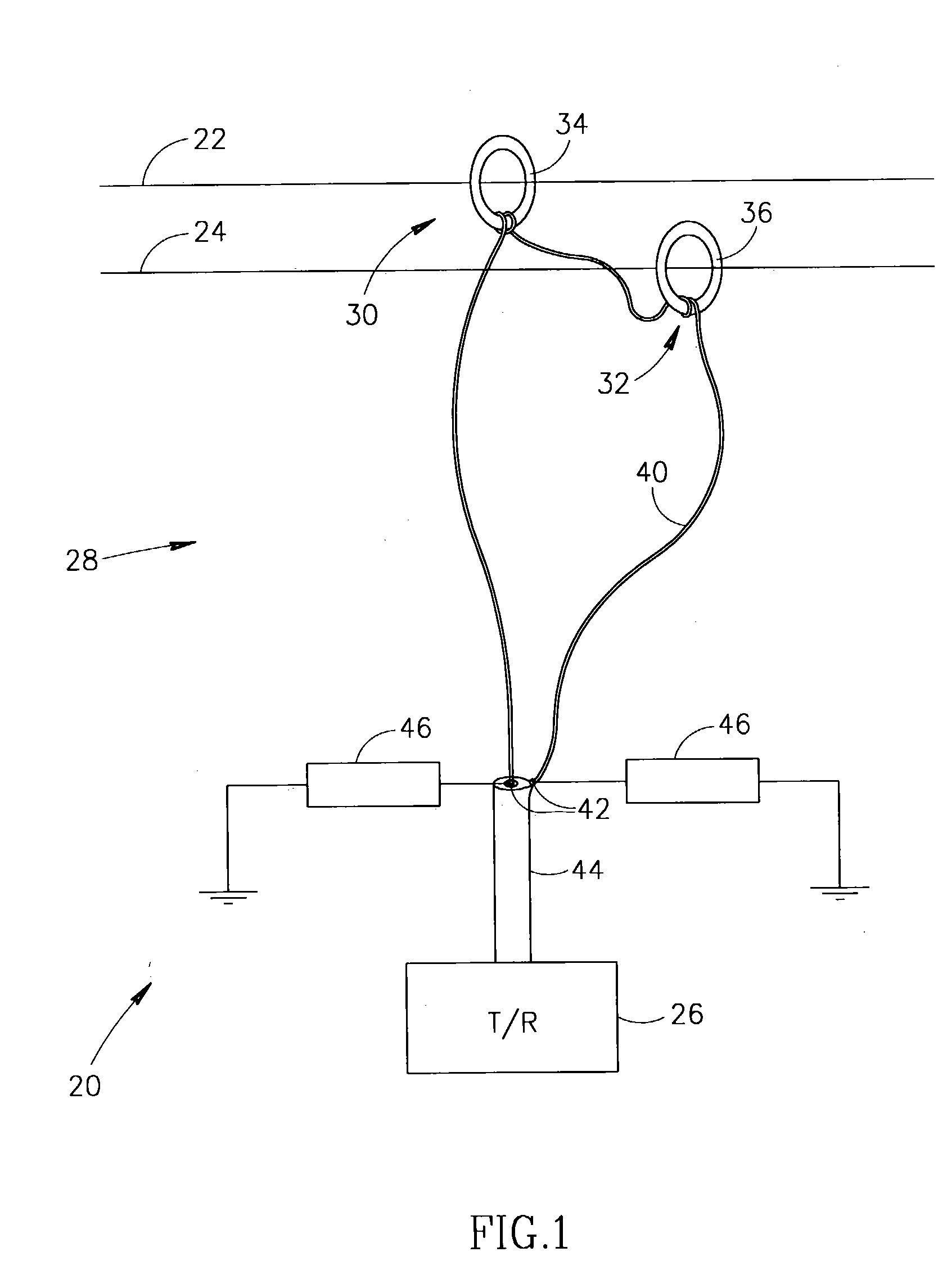
[0057] FIG. 1 schematically shows a system 20 for transmitting data signals over a pair of lines 22 and 24 in a power line network, in accordance with an embodiment of the present invention. System 20 is suitable for transmitting signals over lines in low voltage as well as medium and high voltage power line networks. However, the system is expected to be particularly advantageous for use in transmitting signals over medium and high voltage power line networks, such as for example power line networks that carry voltages in voltage ranges above about 2 Kilovolts. By way of example, lines 22 and 24 are assumed to be above ground lines in a medium or high voltage power line network. Both lines 22 and 24 may be high voltage lines or one of lines 22 and 24 may be a neutral line in the power line network. Lines 22 and 24 generally run parallel to each other distanced by a safety distance required due to the voltage levels they carry. Although the present invention may be employed with lin...


PUM


Abstract

A method of transmitting data over lines of power line network comprising: inductively generating opposite polarity currents representing the data on first and second lines of a pair of lines of the network at a first location along the lines that propagate along the lines; and sensing the propagated currents at a second location along the lines.

Description

[0001] The present application is a continuation-in-part (CIP) of PCT Application No. PCT / IL02 / 00454, filed on Jun. 12, 2002, which claims the benefit under 35 U.S.C. .sctn.119(e) of U.S. Provisional Application No. 60 / 297,643, filed on Jun. 12, 2001, the disclosure of which is incorporated herein by reference.[0002] The invention relates to transmission of data and in particular to transmission of data over power lines.[0003] It is known to use power lines and power line networks to transmit data. An industry standard protocol referred to as CEBus has been established for data transmission between appliances sensors and control devices in a household over the power network in the household. Utility companies use power lines to transmit data to control and monitoring base stations from sensors that monitor power line equipment, such as transformers and switches, and / or power line operating conditions at different locations along a power line.[0004] Transmitters and receivers (herein...

Claims


Application Information

Patent Timeline
IPC IPC(8): H04B3/56
CPCH04B3/56H04B2203/5425H04B2203/5491H04B2203/5479H04B2203/5483H04B2203/5458
Inventor ZALITZKY, YESHAYAHUKERET, JACOB
Owner MAIN NET COMM
Why Eureka
Try Eureka