Combustion emission estimation with flame sensing system

Inactive Publication Date: 2004-02-19
ABB INC
View PDF10 Cites 37 Cited by
  • Summary
  • Abstract
  • Description
  • Claims
  • Application Information

AI Technical Summary

Benefits of technology

0091] As shown in FIG. 9, each burner has a NOx estimator combining the weighted sum of all pertinent measures, where those weightings are adjusted recursively online by the weighting adjustment sc

Problems solved by technology

This technique achieves only global emission control since the behavior of each burner is not observed, even though the burners might be different from one another.

Method used


Image

  • Combustion emission estimation with flame sensing system
  • Combustion emission estimation with flame sensing system
  • Combustion emission estimation with flame sensing system

Examples


Embodiment Construction

(s)

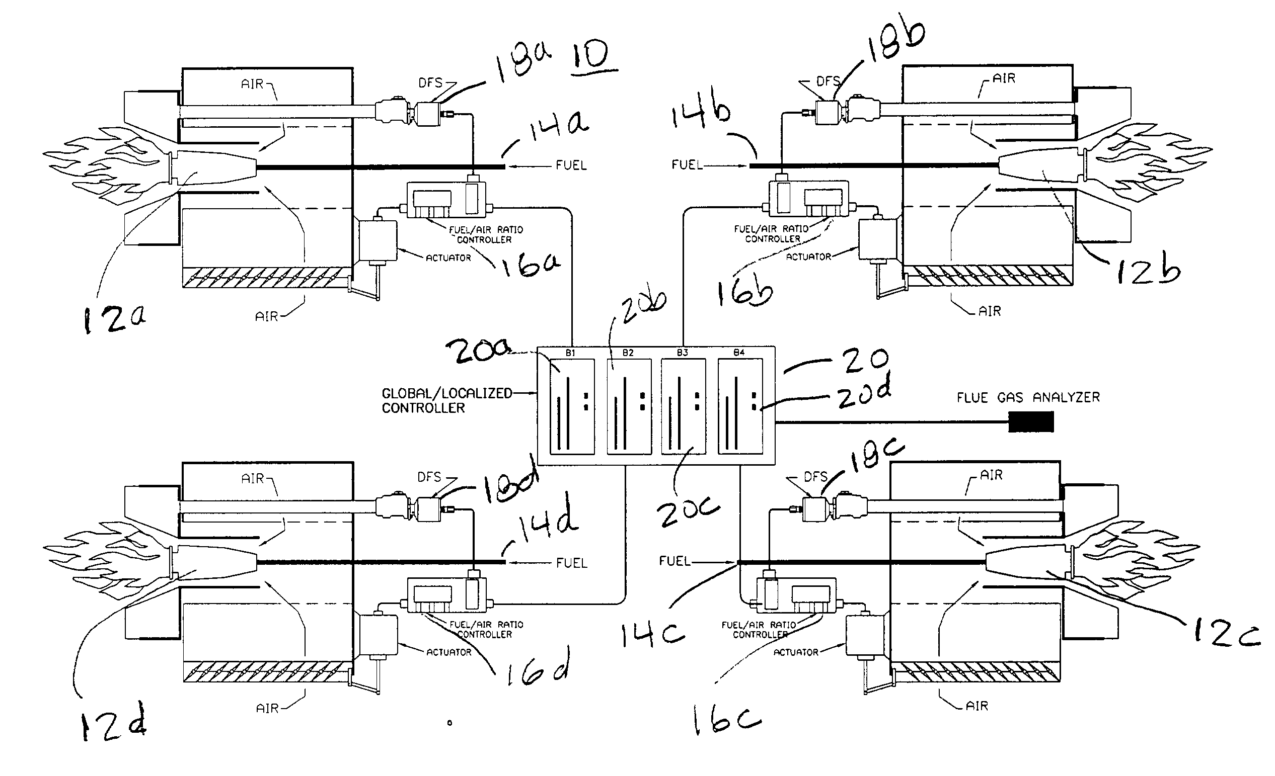
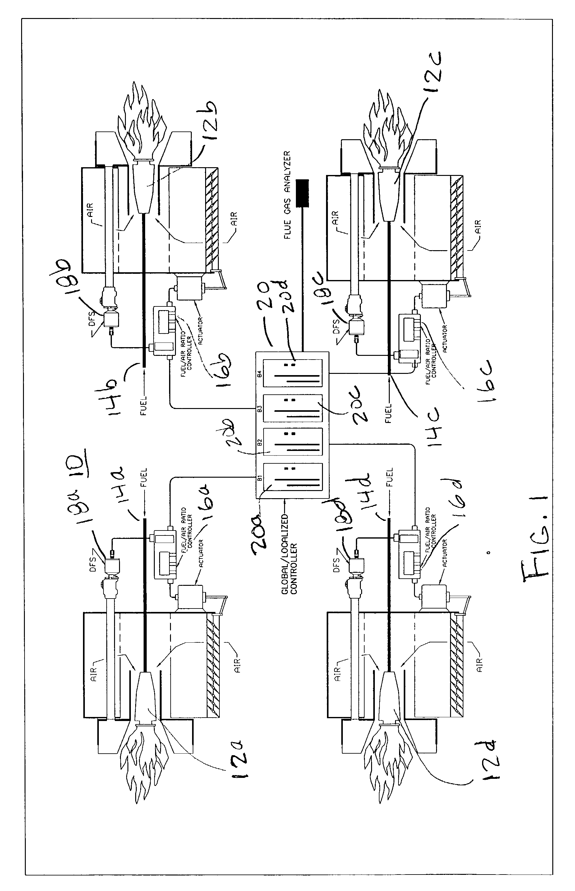
[0037] The present invention is described below in connection with the control of a a particular combustion byproduct formation rate, namely, NOx formation rate, and the embodiment described herein uses a DFS to sense the flame at a burner. As will be appreciated by those of ordinary skill in the art after reading this description of the preferred embodiment, the present invention can be used to control the formation rate of any combustion byproduct and can use any flame scanner that meets the criteria described herein.

[0038] NOx is formed from several sources and can, depending on the source, be classified as fuel NOx, thermal NOx and prompt NOx. Fuel NOx comes from the oxidation of organically bound nitrogen in fuel and is affected by the mixing of fuel and air and by the local 02 cone as well. Thermal NOx results from the thermal fixation of molecular N.sub.2 and O.sub.2 in the combustion air at a temperature higher than 2000.degree. F. The formation of thermal NOx is extremel...


PUM


Abstract

There is described a method and apparatus for controlling the combustion by-product formation rate in at least one burner of a fossil fuel fired power plant. The burner has an associated flame scanner which is focused on a small area of the burner flame to obtain an image signal of the flame. A flame signal that represents properties of temporal combustion in the visible light spectrum of the burner is generated from the image signal. Combustion turbulence at the burner is analyzed from the flame signal by a dynamic invariant that has a relationship to the combustion by-product values and different combustion by-product levels at the burner and the combustion turbulence is correlated to the combustion by-product formation rate at the burner. The method and apparatus can also be used to correlated the combustion turbulence at a multiplicity of burners to the associated combustion by-product formation rate.

Description

1. FIELD OF THE INVENTION[0001] This invention relates to methods and apparatus for in-situ observation and estimation of combustion emission while combustion takes place in a fossil fuel fired power plant.2. DESCRIPTION OF THE PRIOR ART[0002] Among different fossil fuels, coal is the nation's most plentiful and readily available domestic fossil fuel source. It accounts for about 55 percent of the power generated in the United States. Greater utilization of this abundant domestic energy resource will be largely contingent upon the development of technologies that mitigate environmental hazards from the combustion of coal. Such technologies include clean coal technologies, gasification, indirect liquefaction, and hybrid power plants partnering coal with renewable energy source.[0003] By government estimates, the country will need at least 1,300 new electric-power plants over the next 20 years. Coal, which already generates more than half of U.S. capacity, is a logical choice to power...

Claims


Application Information

Patent Timeline
IPC IPC(8): F23N5/08
CPCF23N5/082F23N2029/20F23N2029/08F23N2229/08F23N2229/20
Inventor ZHANG, HUICHASE, PAUL H.NIZIOLEK, JAMES M.
Owner ABB INC
Why Eureka
Try Eureka