Small-beam lateral-shear interferometer

a lateral-shear interferometer and small beam technology, applied in the field of interferometry, can solve the problems of difficult to manufacture glass plates less than a few millimeters thick, limited beam w, and inconvenient lateral-shear interferometers

Active Publication Date: 2004-03-18
ENG SYNTHESIS DESIGN
View PDF4 Cites 17 Cited by
  • Summary
  • Abstract
  • Description
  • Claims
  • Application Information

AI Technical Summary

Benefits of technology

0014] Another goal is a device that includes means for eliminating d

Problems solved by technology

A disadvantage of this type of lateral-shear interferometer resides in the fact that the reflected images will not overlap if the beam W is too small relative to the thickness T of the plate 10.
Therefore, the thickness of the glass plate limits how small the beam W can be.
In practice, it is very difficult to manufacture a glass plate less than a few millimeters thick with very precise flat surfaces and a shear wedge therebetween.
Thus, conventional lateral-shear interferometers are not suitable for testing beams less than about 5-8 mm in diameter.
Although this design of lateral-shear interferometer is advantageously suitable for small-beam applications, it suffers from several drawbacks that disadvantage its commercial utilization.
Because antireflection coatings are not perfect and cannot work over a broad range of wavelengths, the resulting fringe image r

Method used


Image

  • Small-beam lateral-shear interferometer
  • Small-beam lateral-shear interferometer
  • Small-beam lateral-shear interferometer

Examples


Embodiment Construction

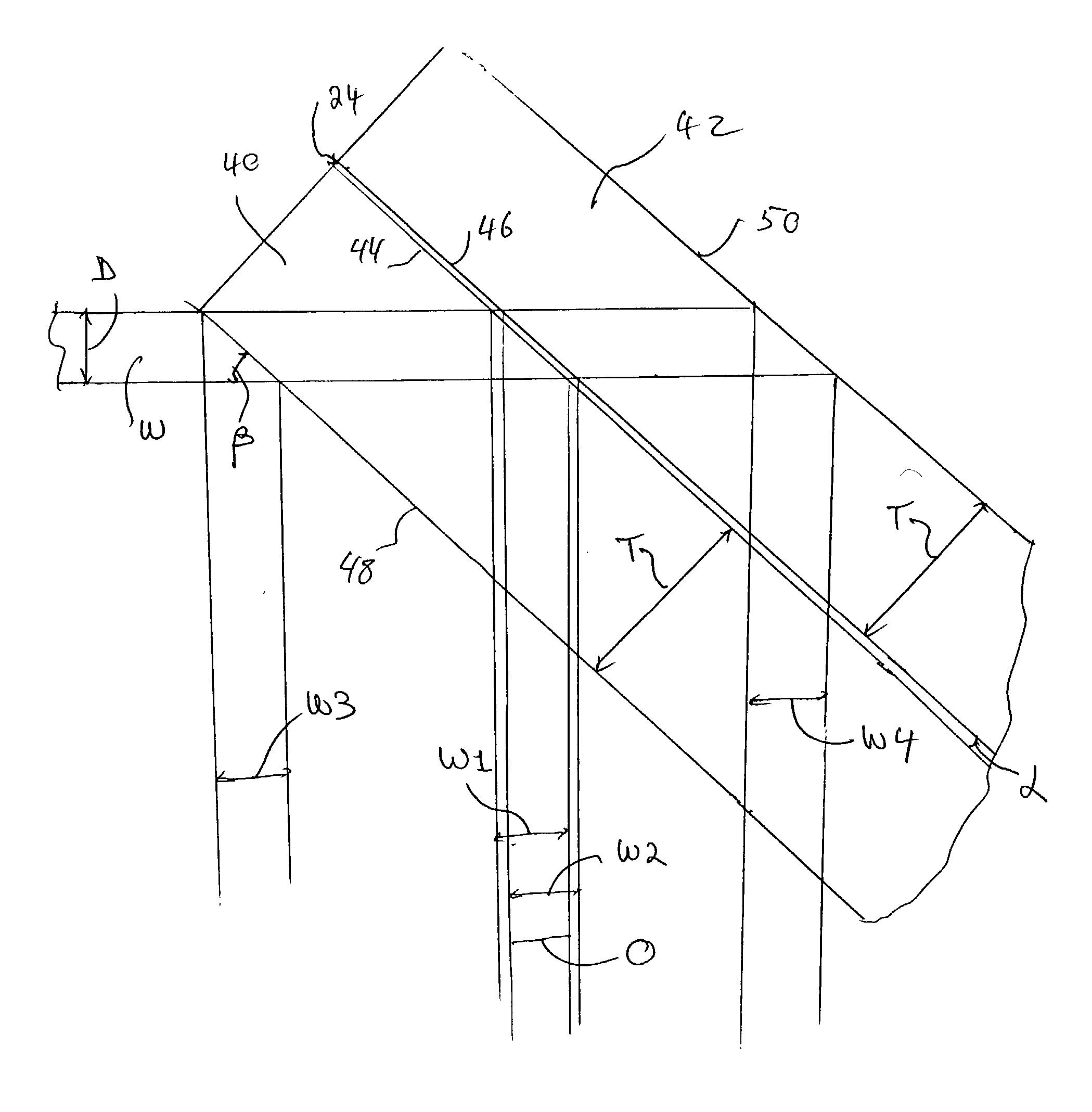
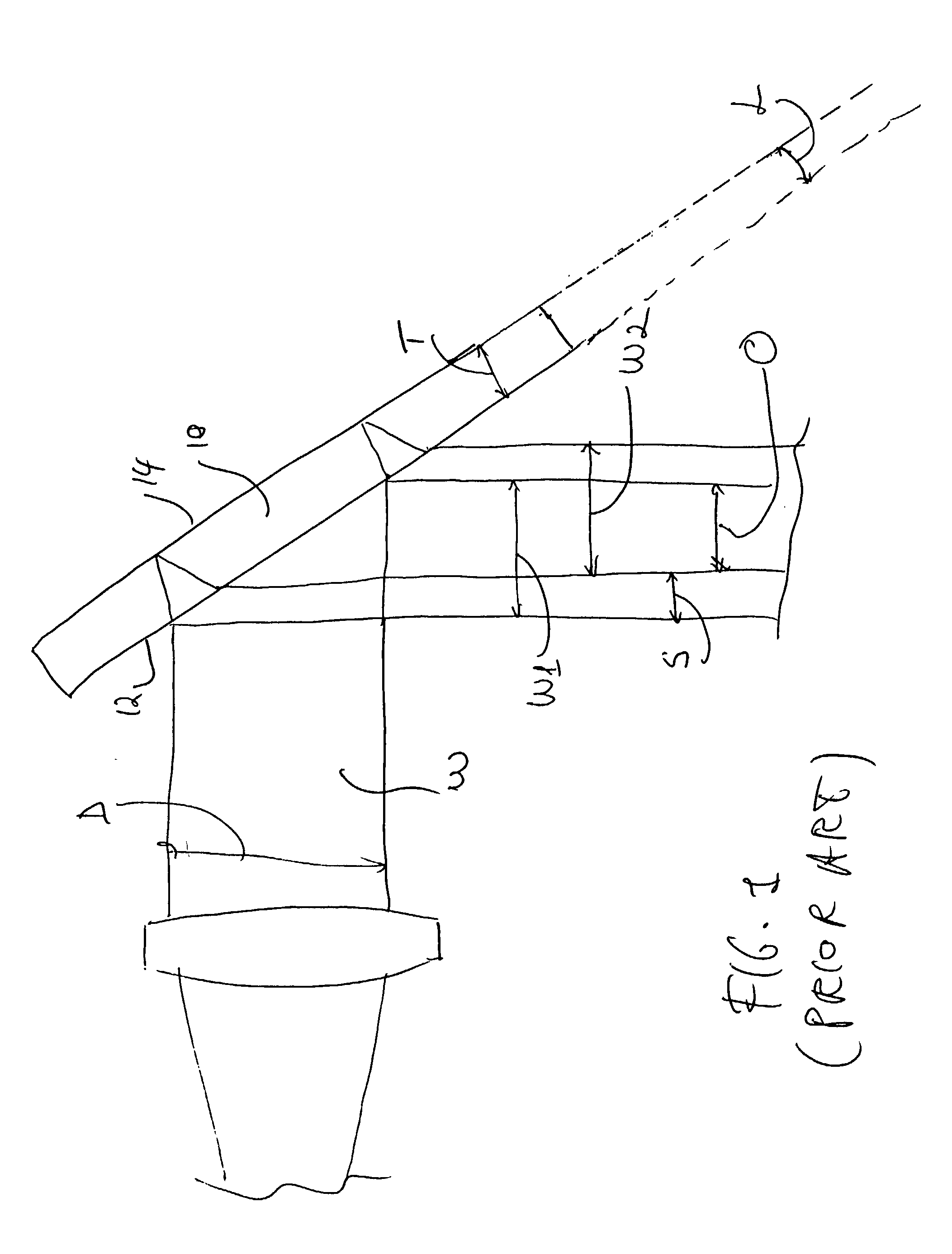
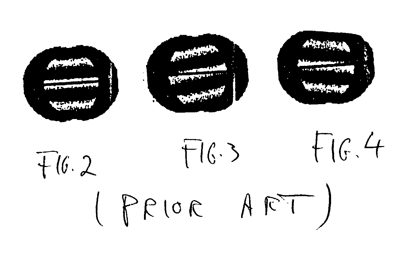
[0030] One aspect of the present invention lies in the recognition that the interference problems arising from the reflection produced by the outer surfaces of conventional dual-plate lateral-shear interferometers can be essentially eliminated simply by increasing the thickness of each plate. The invention further lies in the discovery that the combination of a lateral-shear interferometer with a tilting reflective surface in the optical path of the incoming beam can be used advantageously to produce phase shifts in the pattern of interferometric fringes observed at the output of the device. Thus, the lateral-shear interferometer of the invention, in addition to its simpler process of manufacture, can also be used as an alternative to much more complicated and expensive prior-art devices to carry out phase-shifting interferometry.

[0031] As used herein, the terms "two-plate" and "dual-plate" are used interchangeably to refer to lateral-shear interferometers wherein the beam displacem...


PUM


Abstract

A lateral-shear interferometer utilizes two relatively thick glass plates bonded together in a single block with a tilted air gap between opposing inner surfaces. The thickness of the glass plates is selected to be sufficiently large to separate the output beams from the light reflected from the top and bottom surfaces of the block, thereby eliminating the need for antireflection coatings. The shear interferometer is combined with an external mirror mounted on a tilt stage actuated by a computer-controlled tilt actuator to perform phase-shifting interferometric analysis in conventional manner.

Description

[0001] 1. Field of the Invention[0002] This invention is related in general to the field of interferometry and, in particular, to an improved approach for testing small light beams by lateral-shear interferometry.[0003] 2. Description of the Related Art[0004] Lateral-shear interferometry is known in the art as a method of testing optical components, including the testing of collimation of light beams. The method consists of displacing a wavefront laterally by a small amount and obtaining an interference pattern between the original and the displaced wavefronts. A simple and common physical arrangement to obtain lateral shear consists of two plane glass surfaces used as beam dividers and by the introduction of a small tilt between the surfaces.[0005] Such devices are commercially known as shear-plate interferometers. As shown in FIG. 1, a thin glass plate 10 is positioned at approximately 45-degree angle to an incident light beam W of predetermined width or diameter D produced by a s...

Claims


Application Information

Patent Timeline
IPC IPC(8): G01B9/02
CPCG01J9/0215
Inventor ERWIN, J. KEVIN
Owner ENG SYNTHESIS DESIGN
Why Eureka
Try Eureka