

Anti-diffraction and phase correction structure for planar magnetic transducers
a planar magnetic transducer and phase correction technology, applied in the field of acoustic devices, can solve problems such as negative interference with sound waves, and achieve the effects of minimizing phase distortion, minimizing diffraction of main sound waves, and minimizing the effects of reflected sound waves
- Summary
- Abstract
- Description
- Claims
- Application Information
AI Technical Summary
Benefits of technology
Problems solved by technology
Method used
Image

Examples
Embodiment Construction
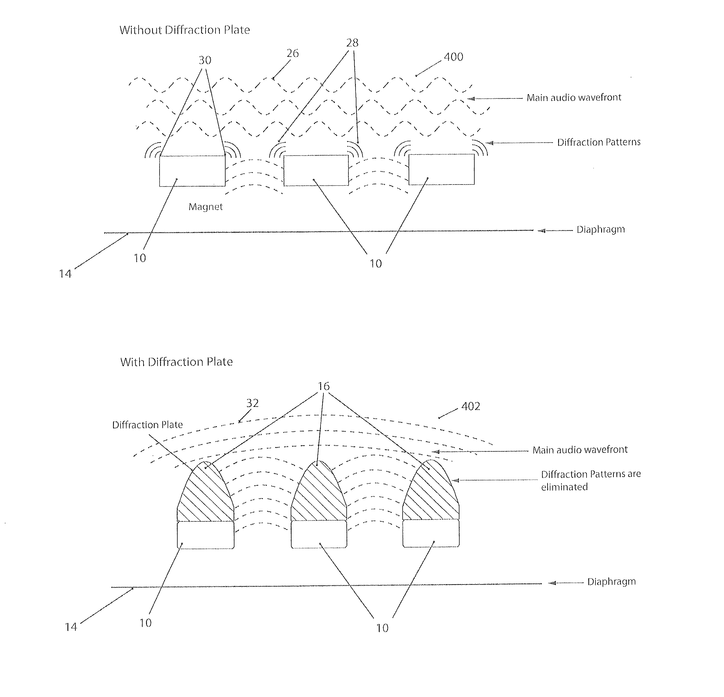
[0005]Preferred embodiments of the invention include a planar magnetic transducer that minimizes diffraction of the main sound wave, minimizes the effects of reflected sound waves and minimizes the phase distortion.
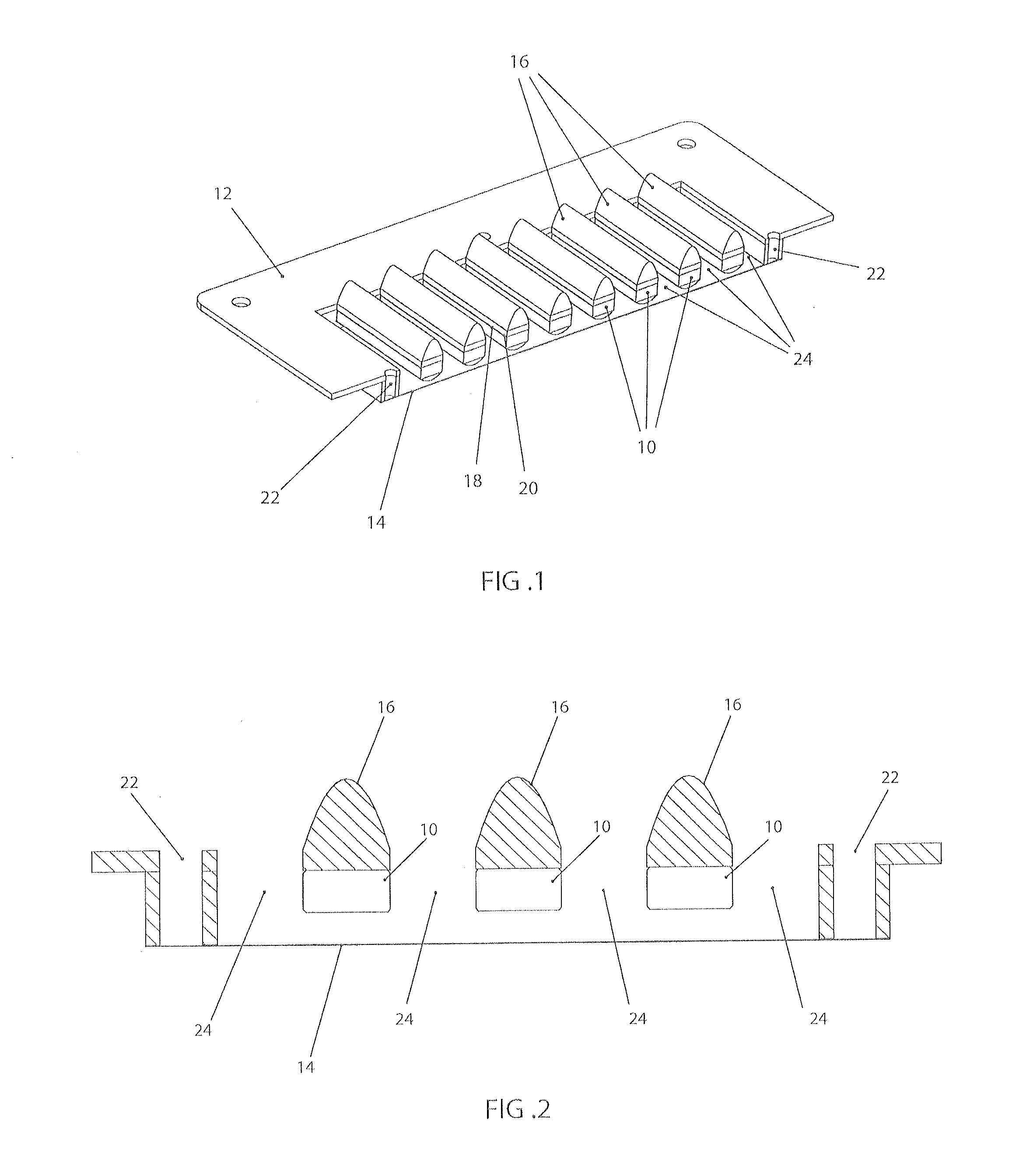
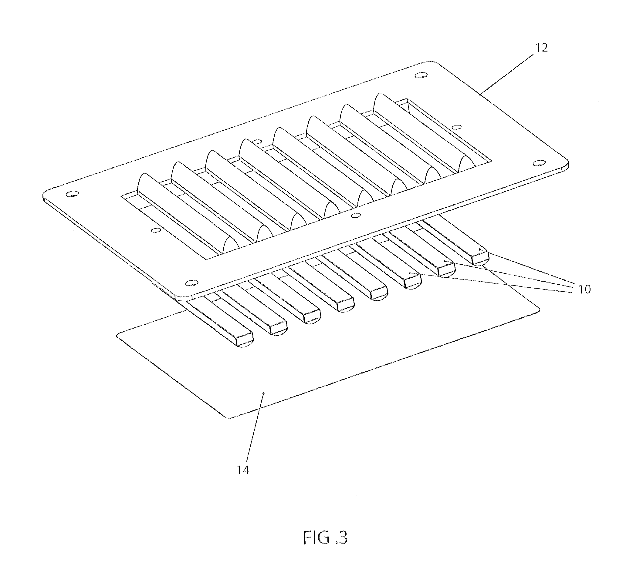
[0006]A preferred embodiment of the invention includes a planar magnetic transducer having one or more anti-diffraction structures positioned adjacent to one or more magnets for eliminating diffraction of a sound wave around the magnets, the sound wave emitted from a diaphragm and passing by the magnets.
[0007]A preferred embodiment of the invention includes a planar magnetic transducer having one or more diffusion structures positioned adjacent to one or more magnets for minimizing reflections of the sound wave.
[0008]A preferred embodiment of the invention includes a planar magnetic device having one or more wave guides positioned adjacent to one or more magnets for creating a uniform wavefront.
BRIEF DESCRIPTION OF THE DRAWINGS
[0009]Preferred embodiments of the present in...
PUM
 Abstract
Description
Claims
Application Information