Directional loudspeaker unit

a loudspeaker unit and directional technology, applied in the direction of transducer details, electrical transducers, electrical apparatus, etc., can solve the problem of difficulty in achieving constant directivity, and achieve the effect of constant directivity

Inactive Publication Date: 2005-09-27
ROBERT BOSCH CO LTD +1
View PDF16 Cites 25 Cited by
  • Summary
  • Abstract
  • Description
  • Claims
  • Application Information

AI Technical Summary

Benefits of technology

[0004]Even with a horn having a diffraction slot, however, it is difficult to attain constant directivity when the driven frequency approaches the upper end of the passband. Preferred embodiments of the present invention address this problem by adding a toroid or other centrally-apertured phase plug of de

Problems solved by technology

Even with a horn having a diffraction slot, however, it is difficult to attain cons

Method used


Image

  • Directional loudspeaker unit
  • Directional loudspeaker unit
  • Directional loudspeaker unit

Examples


Embodiment Construction

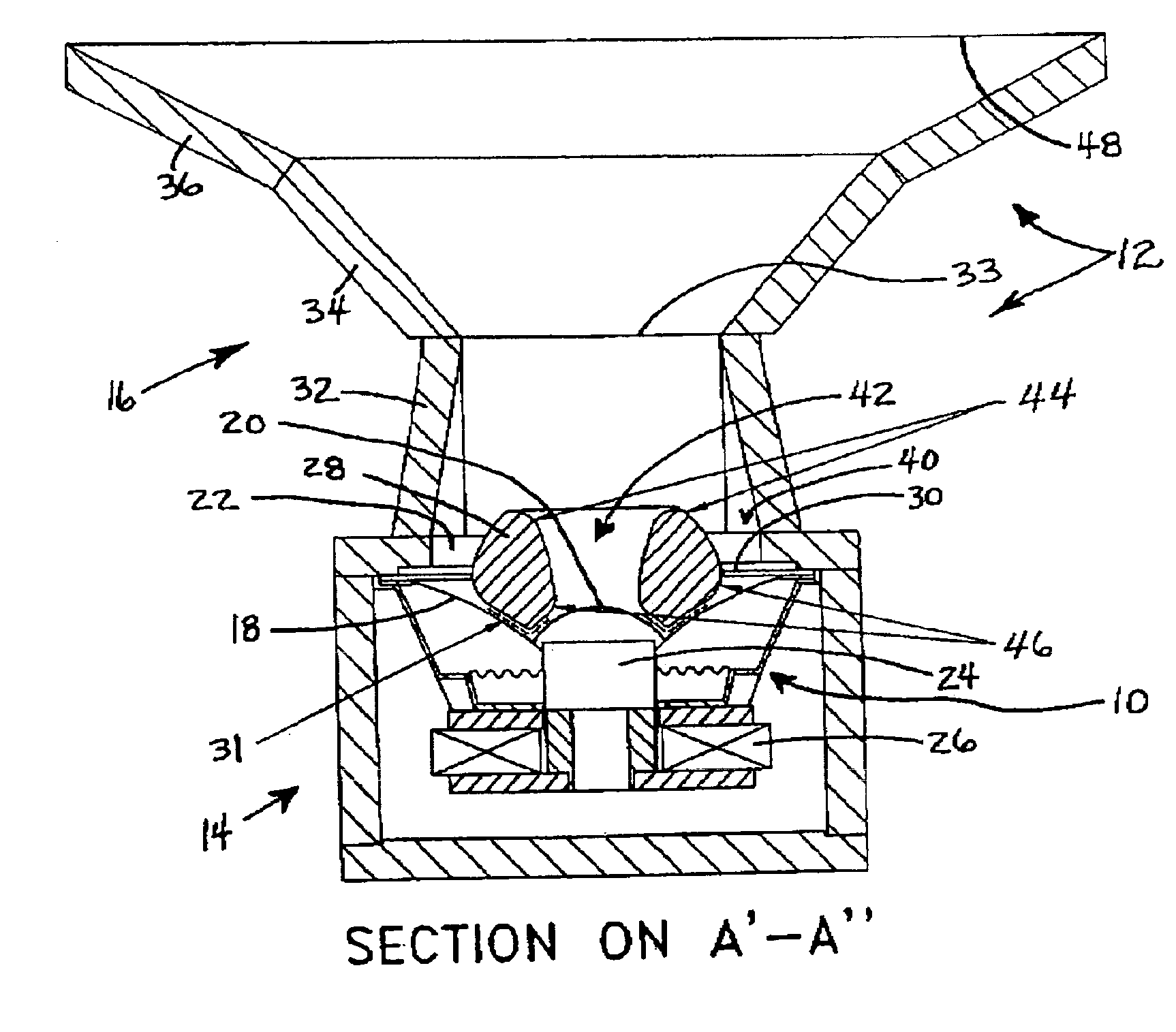
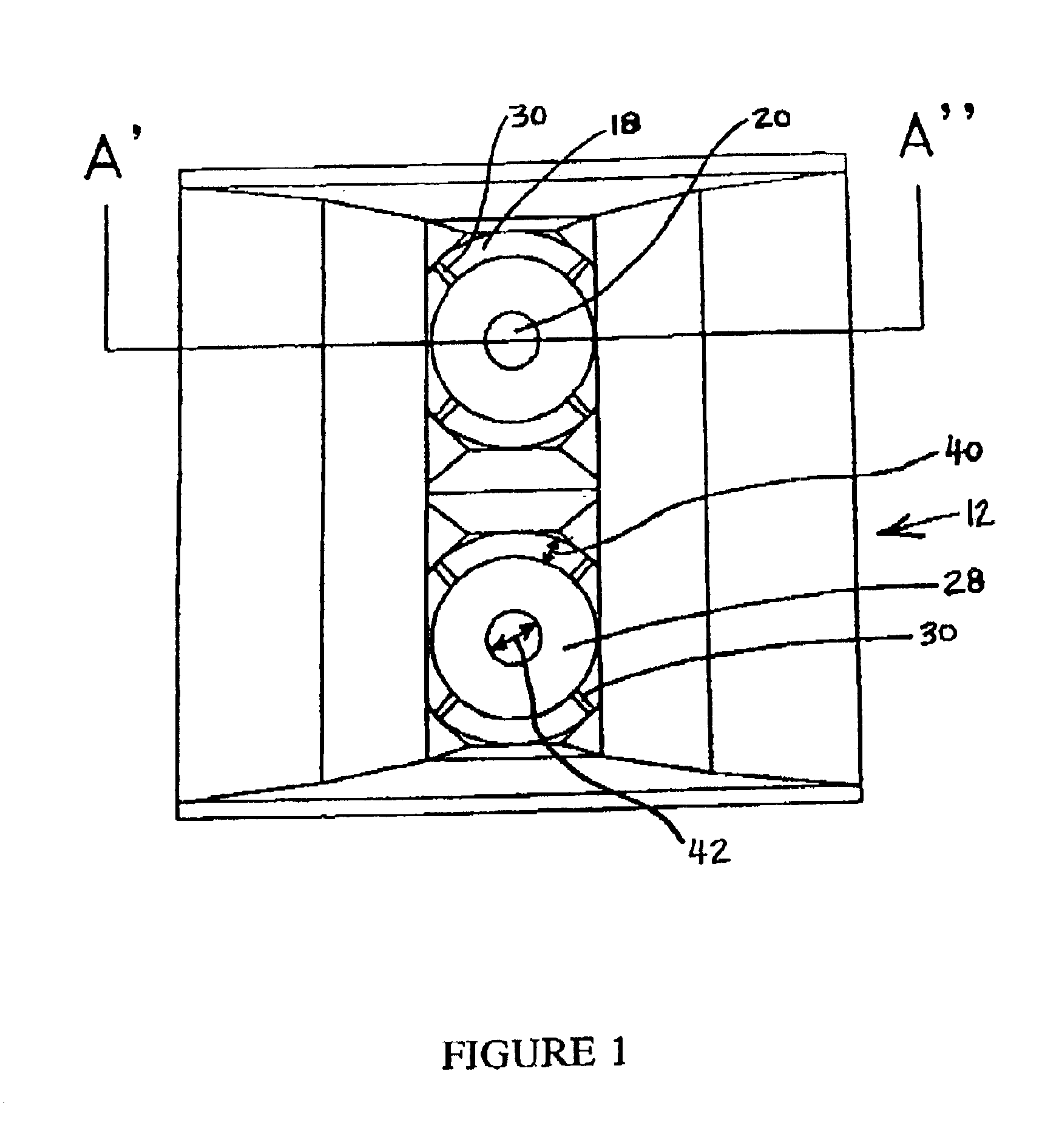
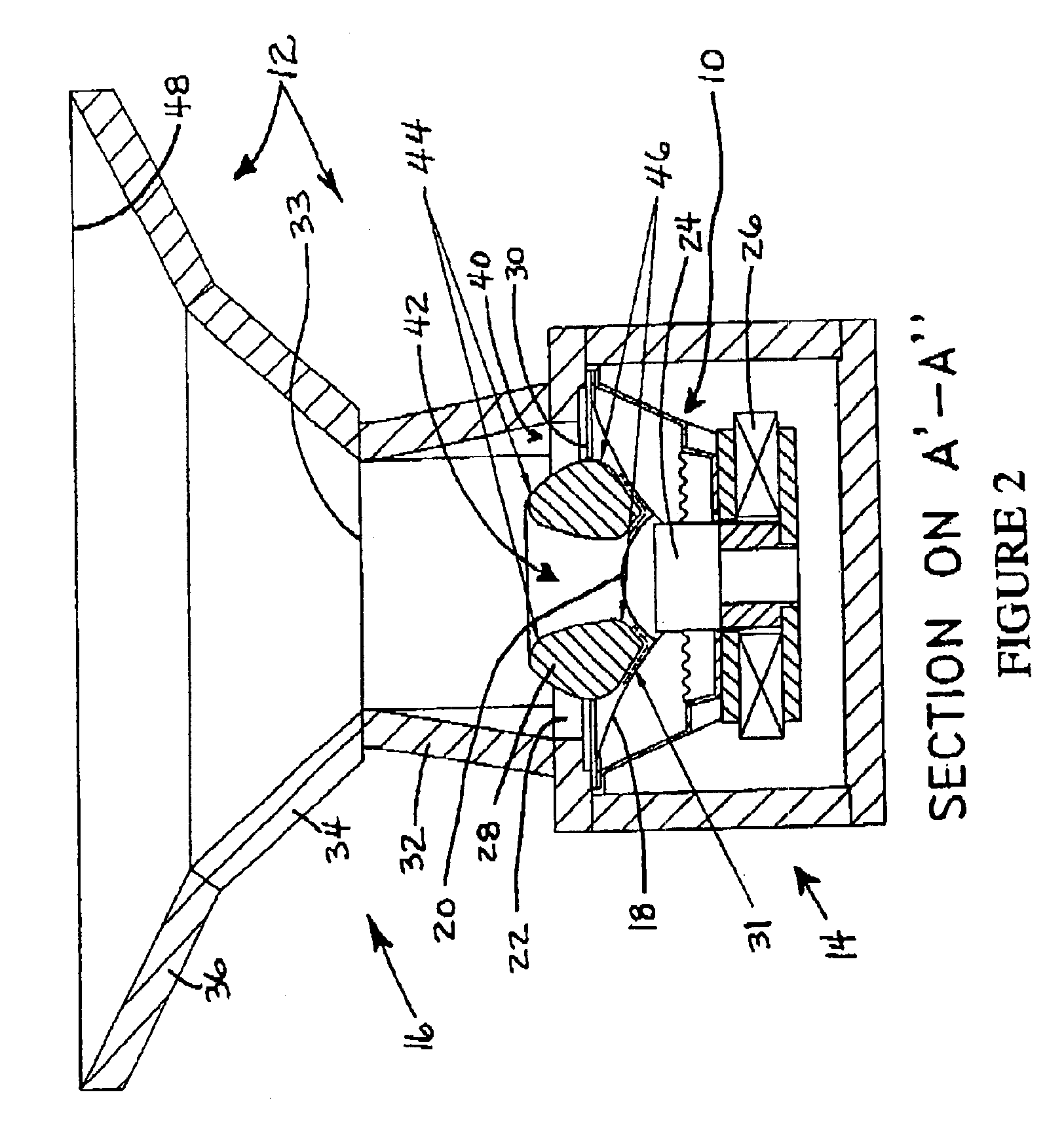
[0031]As shown in FIGS. 1 and 2, in the first embodiment a pair of cone loudspeakers generally designated 10 are mounted within a housing generally designated 12. The housing 12 has a rectangular box portion 14 and an integral rectangular horn portion 16 common to both speakers 10. The pair of cone loudspeakers 10 are mounted in tandem on a front side of the rectangular box portion 14 such that the respective cone 18 and centred dust dome 20 of each loudspeaker face outwardly through an aperture 22 forming the mouth (throat) of the horn 16. As can be seen from FIGS. 1 and 2 together, the aperture 22 is approximately circular, and substantially equal in diameter to the circular cone 18. As shown in the cross-sectional view of FIG. 2, each cone 18 is connected to a former 24 which oscillates at the frequency of a signal being applied to a magnetic coil 26.

[0032]In front of each cone 18 a generally-toroidal phase plug 28 is mounted by webbed support members 30 to sit in the plane of th...


PUM


Abstract

A directional loudspeaker unit for reproducing mid-range audio frequencies, comprising a cone loudspeaker and, disposed forwardly of the surface of the cone of the loudspeaker, a phase plug and a horn, wherein the phase plug and preferably also the horn are arranged co-axially on the axis of the cone, and wherein the phase plug has a central aperture. Preferably the horn has a diffraction slot defined by lateral walls which converge from the entrance (throat) of the horn.

Description

BACKGROUND OF THE INVENTION[0001]This invention relates to a directional loudspeaker unit, and more particularly to a loudspeaker unit having a horn with an acoustic output having a substantially phase-coherent radiating wavefront.[0002]Adding a horn to a loudspeaker increases acoustic output of an associated driver unit in non-uniform manner, by causing the maxima (greatest value) of acoustic output to occur typically in the lower octaves of the operating band (the operating band is also referred to as the “passband”). The position of the maxima with respect to frequency is determined by the geometry of the horn, primarily the mouth area and depth of the horn. As the frequency increases from the frequency associated with the maxima in acoustic output, the output of a loudspeaker with a horn tends toward that of a loudspeaker without a horn. Transition smoothness of acoustic output as frequency increases from the frequency associated with the maxima depends on horn geometry, and pri...

Claims


Application Information

Patent Timeline
IPC IPC(8): H04R1/34H04R1/32
CPCH04R1/345
Inventor BAIRD, JASONWEBB, WILLIAM T.
Owner ROBERT BOSCH CO LTD
Why Eureka
Try Eureka