
Small angle optical beam steering using micro-electro-mechanical system (MEMS) micro-mirror arrays (MMAS)

a micro-mirror array and optical beam technology, applied in the field of optical beam steering, can solve problems such as impracticality of approach, and achieve the effects of minimizing diffraction effects, reducing wavefront distortion of transmitted beams, and minimizing diffraction effects

Active Publication Date: 2022-07-21
RAYTHEON CO
View PDF0 Cites 0 Cited by
  • Summary
  • Abstract
  • Description
  • Claims
  • Application Information

AI Technical Summary

Benefits of technology

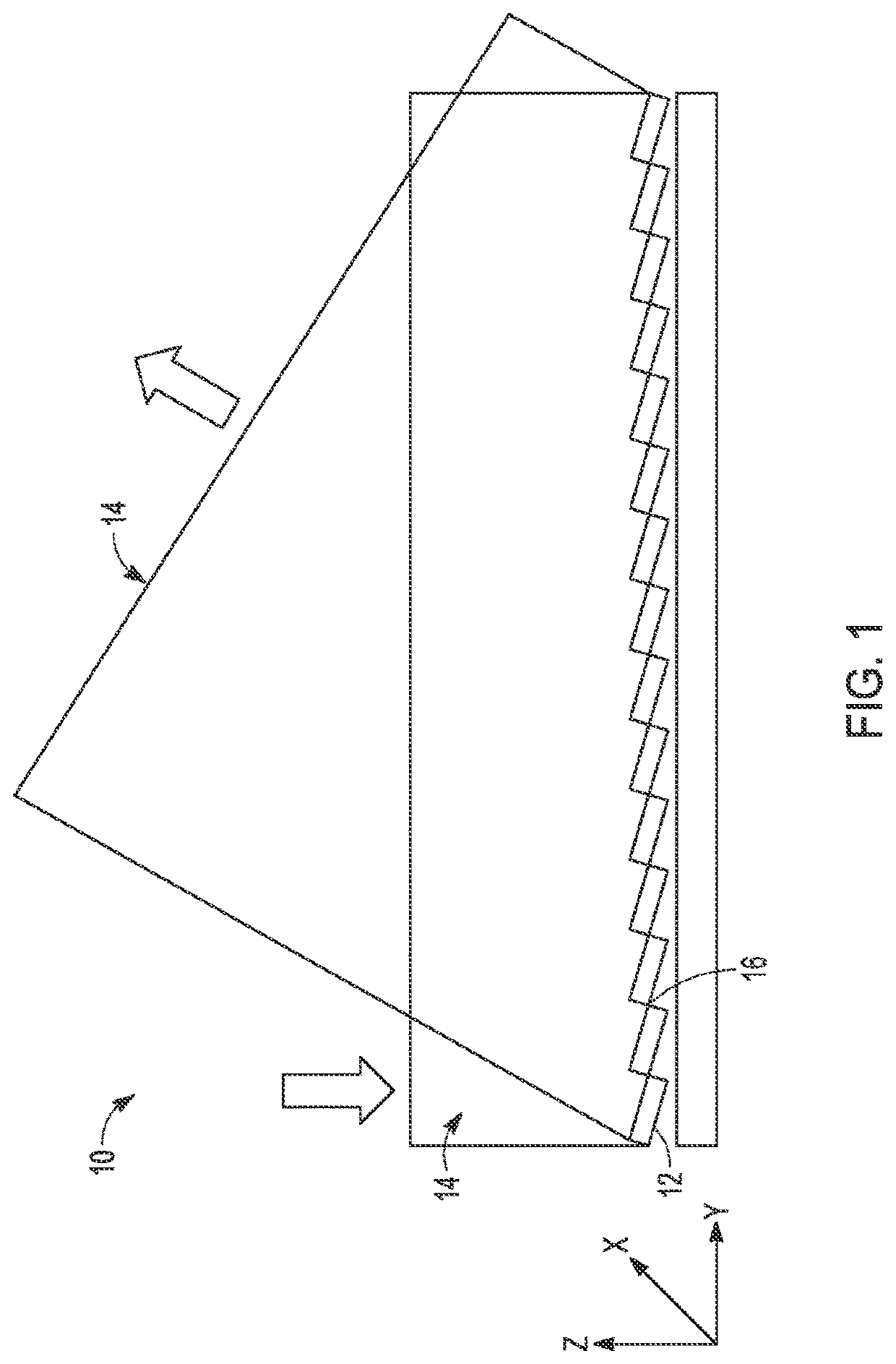
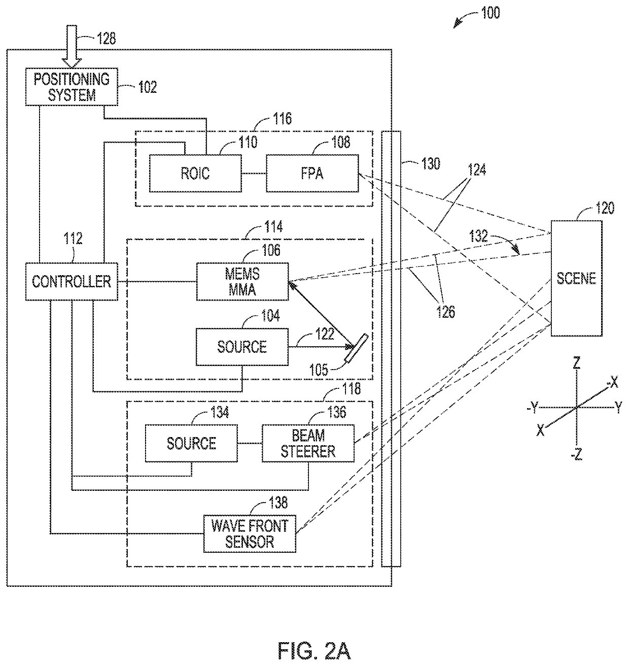
The present invention is about using a MEMS (Micro-Electro-Mechanical System) to steer small optical beams and minimize distortion. The invention uses a MEMS MMA (Micro-Mirror Array) that can be tilted and translated to approximate a continuous surface. By dividing the MMA into sections and actuating them to approximate a continuous surface, the only edge discontinuities exist which minimizes diffraction effects and reduces wavefront distortion of the transmitted beam. This invention also increases imaging resolution in a receive system.

Problems solved by technology

In most applications, loss of steering range would make this approach impractical.
However, in certain applications small angle steering is sufficient, For example, space based systems that operate at long ranges may require only a few degrees of steering to transmit the beam.

Method used


Image

  • Small angle optical beam steering using micro-electro-mechanical system (MEMS) micro-mirror arrays (MMAS)
  • Small angle optical beam steering using micro-electro-mechanical system (MEMS) micro-mirror arrays (MMAS)
  • Small angle optical beam steering using micro-electro-mechanical system (MEMS) micro-mirror arrays (MMAS)

Examples


Embodiment Construction

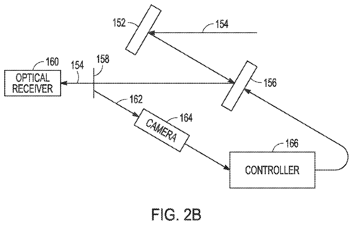
[0022]To overcome limitations of using a waveguide to perform beam steering, another approach is to use a Micro-Electro-Mechanical System (MEMS) Micro-Mirror Array (MMA) to steer a beam of optical radiation. MEMS MMA beam steering may be used in an active system to steer the beam provided by an illumination source or stabilize line of sight for a receiver, passive or active. The MEMS MMA comprises an array of independently and continuously tunable mirrors that can tip and tilt to re-direct the beam. The MEMS MMA typically exhibits a larger steering range and faster speeds than the LCWG. For many applications, the ability to steer the beam quickly over larger angles allows the MEMS MMA to prosecute a larger Field-of-Regard (FOR) than the waveguide approach. Furthermore, the MEMS MMA can be implement for different wavelengths without changing the material system or the beam steering settings. Different wavelengths can be realized by using a plurality of sources at different wavelength...


PUM


Abstract

Small angle optical beam steering is performed using a Micro-Electro-Mechanical System (MEMS) Micro-Mirror Array (MMA) that minimizes diffraction for a specified steering angle, Generally speaking, this is accomplished with a MEMS MMA that exhibits a “piston” capability to translate individual mirrors in addition to the tip and tilt capabilities. Adjacent mirrors can be tipped / tilted to the specified steering angle and then translated by a requisite amount to approximate a continuous surface. For a specified steering angle, the MEMS MMA is partitioned into one or more sections with each section including the maximum number of mirrors that can be grouped together and actuated to approximate a continuous surface given a maximum translation z. As a result, the only edge discontinuities exist between adjacent sections thereby minimizing distortion for a given steering angle.

Description

BACKGROUND OF THE INVENTIONField of the Invention[0001]This invention relates to optical beam steering, and more particularly to small angle optical beam steering using Micro-Electro-Mechanical System (MEMS) Micro-Mirror Arrays MMAS).Description of the Related Art[0002]Active optical systems use laser radiation to illuminate a scene. In various conventional approaches, an illumination source is positioned to continuously illinate an entire scene within a Field of View (FOV). Such illumination sources consume a great deal of power. Other approaches have suggested positioning beamforming optics on a gimbal system, which would allow mechanical movement of the system to scan the scene to reduce power consumption. However, with these typical solutions the cost and weight of the associated system significantly increases while the speed of the system decreases.[0003]Another approach is to use a waveguide such as a liquid crystal waveguide (LCWG) to steer a beam of optical radiation provide...

Claims


Application Information

Patent Timeline
Patent Type & Authority Applications(United States)
IPC IPC(8): G02B26/08
CPCG02B26/0833
Inventor UYENO, GERALD P.LANGE, MARK K.KELLER, SEAN D.GLEASON, BENN H.BARKER, ZACHARY D.SHOTT, CRAIG O.ROGALA, ERIC
Owner RAYTHEON CO
Learn More