
Projection Apparatus, Collection Apparatus, and Three-dimensional Scanning System with Same

Pending Publication Date: 2022-01-06
SHINING 3D TECH CO LTD
View PDF0 Cites 1 Cited by
  • Summary
  • Abstract
  • Description
  • Claims
  • Application Information

AI Technical Summary

Benefits of technology

The patent application describes a projection apparatus that can be used for three-dimensional scanning of objects, including the oral environment. The apparatus is designed to be low cost and compact. It uses multiple rays of light that are transmitted to create a color-coded image of the target object, allowing for the analysis of its shape. The apparatus is able to eliminate the effect of diffraction spots, which can cause difficulty in obtaining accurate shape information. Overall, the patent solves the issues of high cost and limited application of current three-dimensional scanning methods.

Problems solved by technology

However, the above methods for obtaining the three-dimensional shape of the object are not applicable to intra-oral three-dimensional scanning due to own defects as follows: the three-dimensional reconstruction method based on time coding cannot implement handheld scanning, so that a high-precision intra-oral scanning operation cannot be implemented.
Moreover, the cost is high due to the support requirement of a high frame rate camera and a high-speed algorithm.
The method based on the microscopic confocal three-dimensional imaging principle has high hardware processing cost.
At present, no effective solutions have been proposed for the problems that the method for obtaining the three-dimensional shape of an object in the related art is not applicable to an oral environment and is high in cost.

Method used


Image

  • Projection Apparatus, Collection Apparatus, and Three-dimensional Scanning System with Same
  • Projection Apparatus, Collection Apparatus, and Three-dimensional Scanning System with Same
  • Projection Apparatus, Collection Apparatus, and Three-dimensional Scanning System with Same

Examples


Embodiment Construction

[0037]It should be stated that in the case of no conflict, embodiments in the present application and features in the embodiments can be mutually combined. The present application is described below in detail with reference to the drawings and in combination with the embodiments.

[0038]To make those skilled in the art better understand the solutions of the present application, the technical solutions in the embodiments of the present application will be clearly and completely described below with reference to the drawings in the embodiments of the present application. Obviously, the described embodiments are only a part of the embodiments of the present application, not all of the embodiments. All other embodiments obtained by those of ordinary skill in the art based on the embodiments of the present application without creative efforts should fall within the scope of protection of the present application.

[0039]It should be noted that the specification and claims of the present appli...


PUM


Abstract

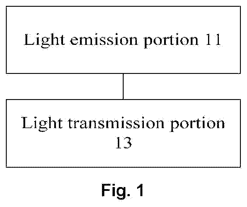
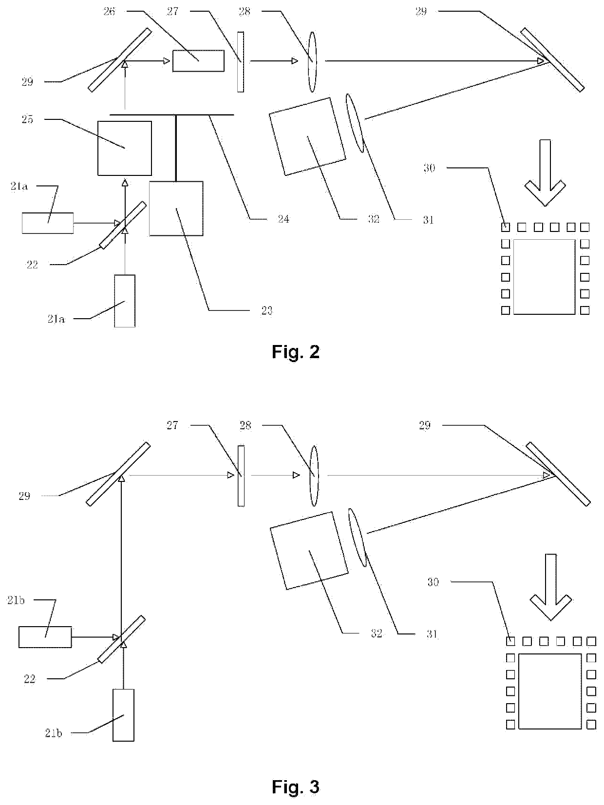
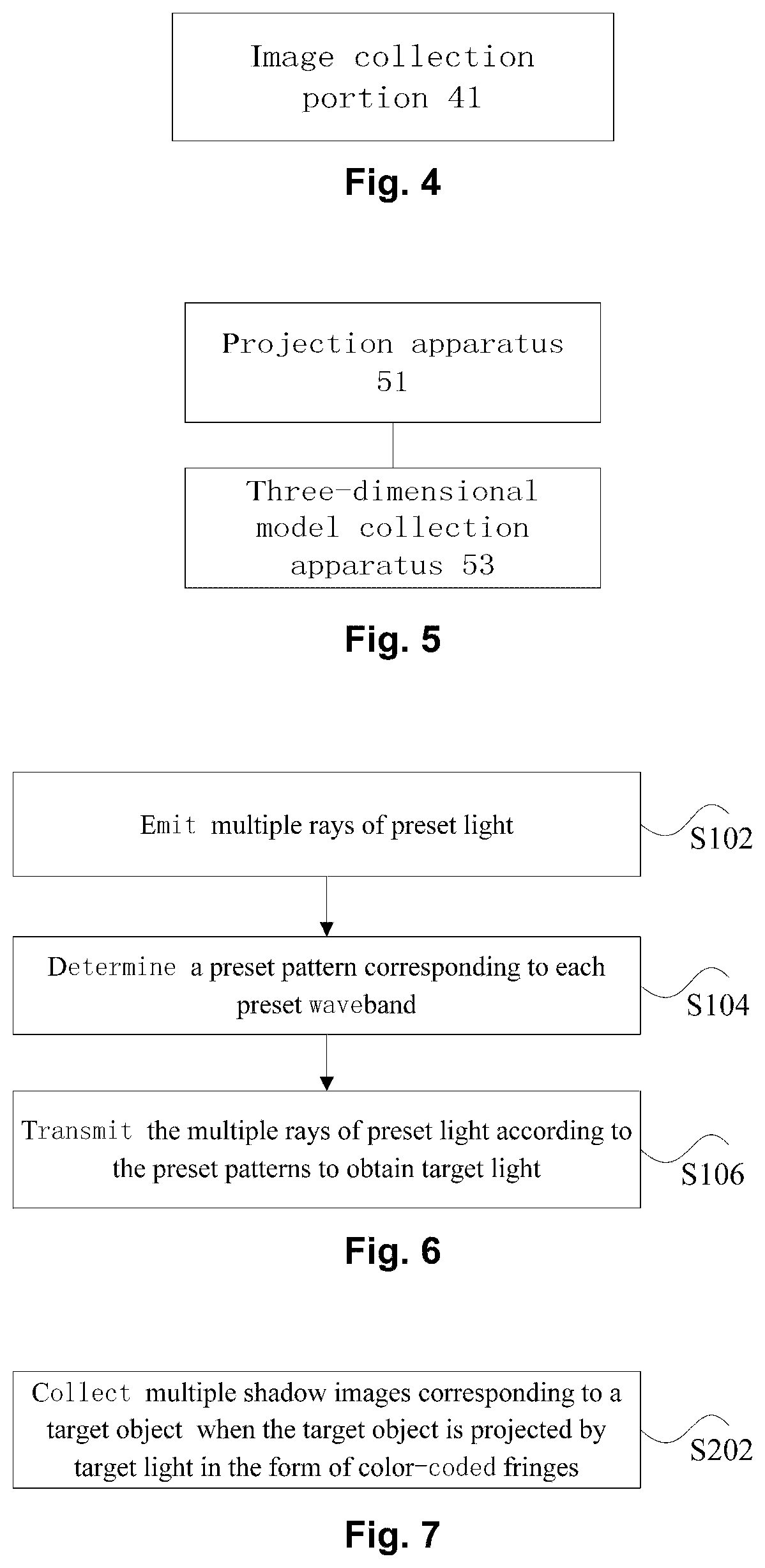
The present application discloses a projection apparatus, a collection apparatus, and a three-dimensional scanning system with the same. The projection apparatus includes: a light emission portion, configured to emit multiple rays of preset light, wherein the multiple rays of preset light correspond to multiple preset wavebands, and the multiple preset wavebands are different from each other; and a light transmission portion, disposed on a transmission path of the rays of preset light, wherein the rays of preset light is transmitted via a preset pattern on the light transmission portion to generate target light projected to a target object in the form of color-coded fringes, and the light transmission portion transmits the rays of preset light corresponding to at least two different preset wavebands.

Description

[0001]The present application claims priority of Chinese Patent Application No. 201811378663.1, filed on Nov. 19, 2018, entitled “Projection Apparatus, Collection Apparatus, and Three-dimensional Scanning System with Same”, the contents of which are hereby incorporated by reference in its entirety.TECHNICAL FIELD[0002]The present application relates to the field of three-dimensional scanning, and in particular to a projection apparatus, a collection apparatus, and a three-dimensional scanning system with the same.BACKGROUND ART[0003]In the existing technology, there are multiple methods for obtaining a three-dimensional shape of an object, specifically including: de-matching sinusoidal fringes based on time coding, performing three-dimensional reconstruction and splicing fusion, and then obtaining the three-dimensional shape of the object; obtaining the three-dimensional shape of the object through algorithms of extracting a fringe center line based on time coding and performing thr...

Claims


Application Information

Patent Timeline
IPC IPC(8): G01B11/25
CPCG01B11/2518G01B11/2509G01B11/2433G01B11/254A61C9/006H04N13/271H04N13/254G06T7/521G06T2207/10024G03B21/2013G03B21/2033G03B21/2066G06T7/60G06T7/90G06T17/30
Inventor MA, CHAOYE, ZI
Owner SHINING 3D TECH CO LTD
Learn More