Multifunctional network interface node

a network interface and multi-functional technology, applied in the field of multi-functional network interface nodes, can solve the problems of limited end-user configurability, system, device limitations, and high complexity of vehicles such as automobiles, and achieve the effects of reducing the number of users, and increasing the number of users

Inactive Publication Date: 2004-03-18
WARREN CHRISTOPHER E +1
View PDF4 Cites 169 Cited by
  • Summary
  • Abstract
  • Description
  • Claims
  • Application Information

AI Technical Summary

Benefits of technology

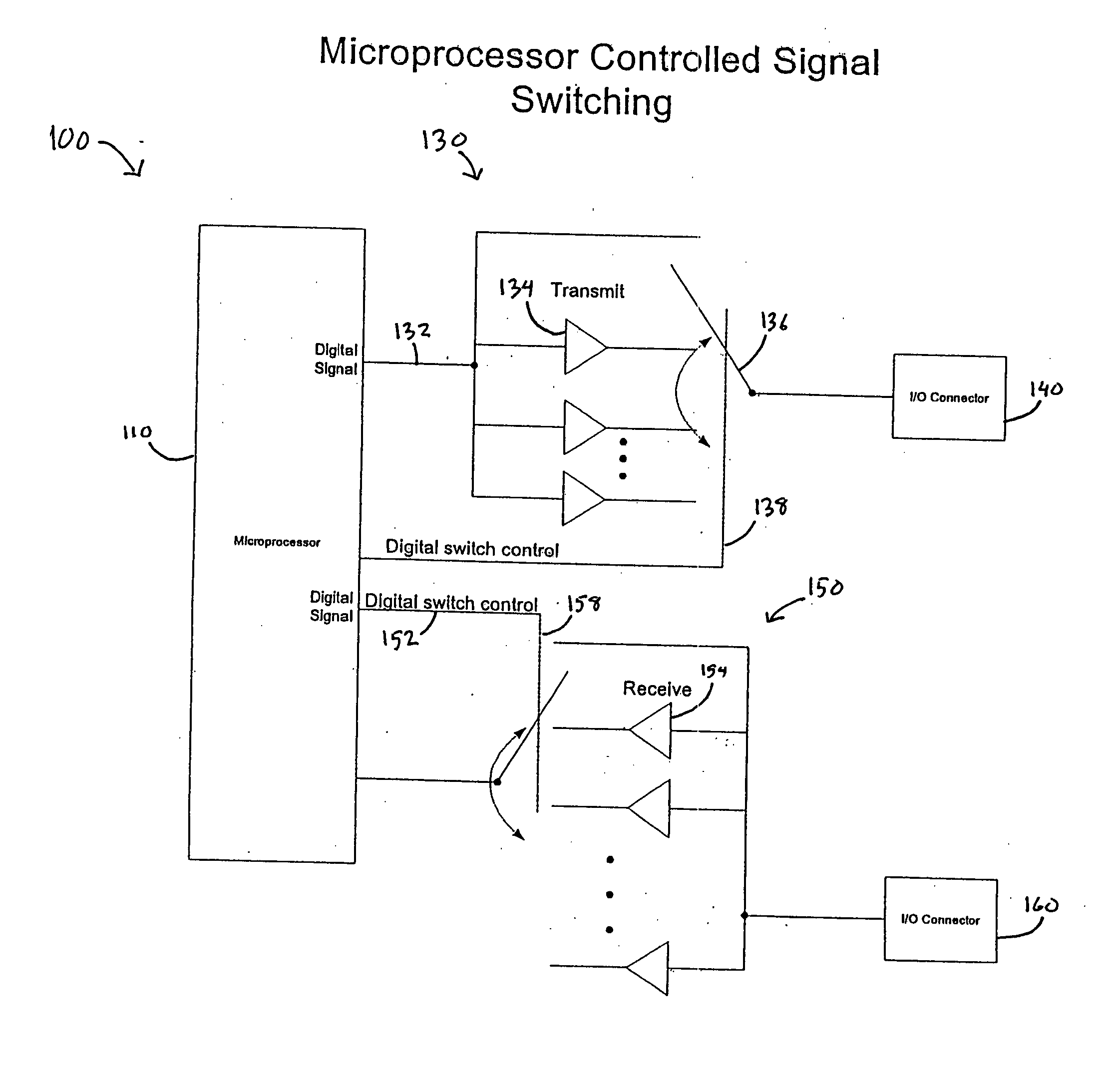
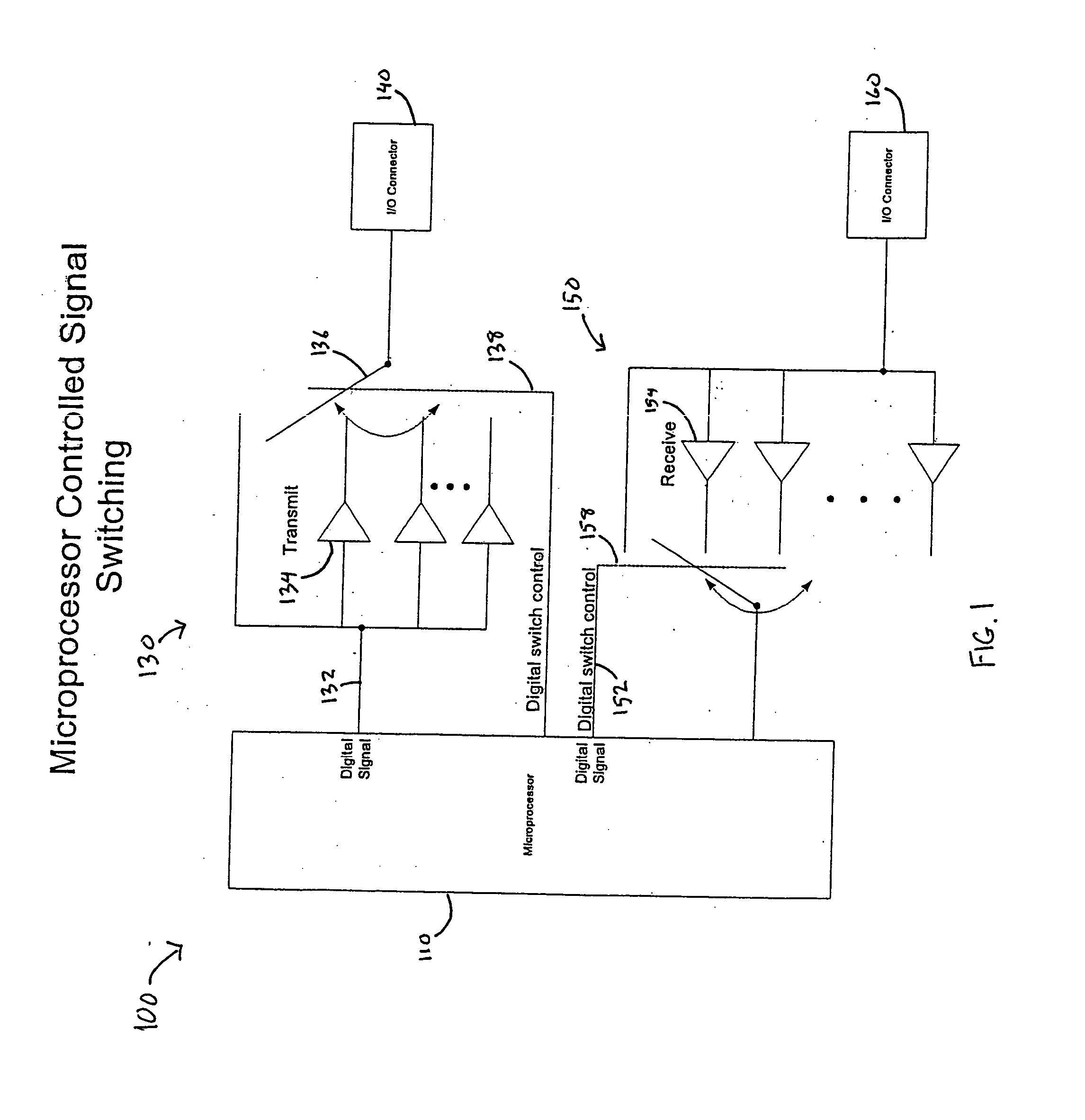
[0018] Therefore, it is an object of this invention to provide a flexible, user-configurable network node which acts as common interface for analog, digital, and serial devices, and devices utilizing other communication formats.
[0019] It is also an object of the present invention to provide a flexible, user-configurable network node that is compatible with a Controller Area Network or any other suitable network.
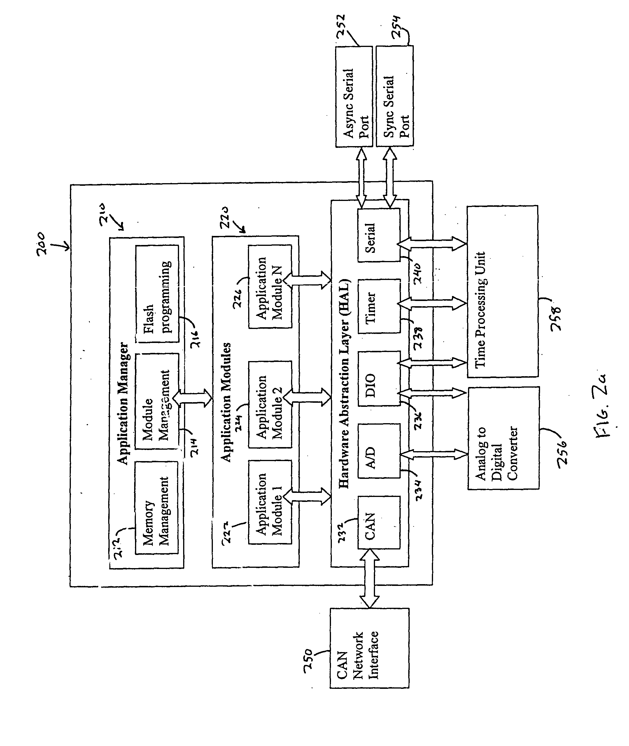
[0020] It is a further object of the present invention to provide a multifunctional network interface node which is expandable and upgradable without removing the hardware following installation of the multifunctional network interface node on a moving platform.
[0021] It is a further object of the present invention to provide a system that enables a user to select from a variety of system devices operating simultaneously and view information gathered by one or more of these devices at a single end-user terminal.
[0022] It is a further object of the present invention to provide a system that will enable a user to control a plurality of devices or subsystems from a single end-user terminal.

Problems solved by technology

Vehicles such as automobiles, military vehicles, recreational watercraft, naval vessels, and aircraft are often highly complex, mobile platforms which include a variety of peripheral devices, sensors, and subsystems.
Despite some functional equivalence, the systems, devices, methods discussed above are subject to significant limitations in that (i) they do not offer a common software interface between various digital, analog, and serial devices; (ii) they are limited in their end-user configurability, and as such are relatively inflexible following installation; and (iii) they offer either no expandability, or only limited expandability, both in terms of software and hardware capabilities.

Method used


Image

  • Multifunctional network interface node
  • Multifunctional network interface node
  • Multifunctional network interface node

Examples


example 1

Sensor Interface and RS-232 / Digital Node

[0169] FIG. 4a illustrates an embodiment of the present invention in which MNIN is operating as a sensor interface and RS-232 / digital interface where there is no interface circuitry between MNIN and the system devices. This "sensor interface node" includes analog sensors which are input to the A / D converter, as well as 5V pulse signals being input through the signal routing path for 5V signals into the microprocessor for performance of calculations. This embodiment also utilizes the signal routing ability of MNIN to include an interface with additional GPS units by switching the appropriate channel to the transmitter and receiver signal path. In this embodiment, the node can operate independently based on input conditions and change the outputs accordingly, or alternatively, the node can provide sensor information to another device connected to the network.

[0170] In FIG. 4a sensor interface and RS-232 / digital interface node 400 is housed withi...

example 2

Power Switch Node

[0171] FIG. 4b illustrates an embodiment of the present invention in which MNIN is configured as power switch node 402 with no interface circuitry between MNIN and the system devices. Power switch node 402 controls a bank of switches that provide power to peripheral devices such as a computer, lights, pumps, etc. To achieve this, the MNIN outputs (on the same multifunctional lines) control signals to the switches and turn them on or off. Depending on the type of switch used, a 5V control signal is utilized by switching to the 5V signal path, or alternatively, a -12 to 12V signal is utilized by switching to transmitter path. Power switch node 402 can be configured to either control switches depending on inputs, or can be controlled by means of the network interface to activate specified circuits. In FIG. 4b relay array 462 is powered by switch array power supply 460 and is connected to a plurality of power switches 464.

example 3

GPS Node

[0172] FIG. 4c illustrates an embodiment of the present invention in which MNIN is configured as GPS node 404 with no interface circuitry between MNIN and the system devices. GPS node 404 communicates with an internal commercial GPS unit 470 that uses 5V signal levels by switching to the 5V signal path, and at the same time communicates with an external GPS unit using .+-.12V signals by switching to the alternate transmitter and receiver paths. Each interface takes advantage of the signal routing ability of MNIN to use the appropriate signal levels without additional circuitry. This embodiment of the GPS node uses the network interface to report information to another device on the network. In FIG. 4c Digital I / O and RS-232 interface connector 430 is in communication with internal commercial GPS unit 470 (digital) and with external GPS interface connector 471 (RS-232) which is connected to an external GPS unit.


PUM


Abstract

A flexible, user-configurable, multifunctional network interface node capable of communicating with and controlling a plurality of system devices, including digital, analog, and serial devices. The network node includes two basic components: (a) user-configurable software which provides a common software interface for different system devices; and (b) hardware which provides a hardware interface for the system devices and executes various functions as directed by the user-configurable software.

Description

BACKGROUND OF INVENTION[0001] The field of the present invention relates generally to systems for operating networked devices and subsystems which utilize different electronic communication formats, and specifically to intelligent electronic nodes that provide common software and hardware interfaces for such devices and subsystems.[0002] Vehicles such as automobiles, military vehicles, recreational watercraft, naval vessels, and aircraft are often highly complex, mobile platforms which include a variety of peripheral devices, sensors, and subsystems. These peripheral devices, sensors, and subsystems, referred to generically as "system devices," permit the operator of the vehicle to control certain aspects of vehicle performance, and to assess the operational efficiency and overall condition of the vehicle at any given time. System devices may include mechanical and electrical devices such as electronic compasses, water temperature sensors, engine and wheel RPM sensors, engine temper...

Claims


Application Information

Patent Timeline
Patent Type & Authority Applications(United States)
IPC IPC(8): H04L29/06
CPCH04L69/18
Inventor WARREN, CHRISTOPHER E.SHOAF, RICHARD L.
Owner WARREN CHRISTOPHER E
Why Eureka
Try Eureka