System and method for measuring the velocity of fluids

a technology of fluid velocity and system, applied in the field of fluid velocity measurement, can solve the problems of complex implementation, complicated use of resistance as measurable parameter, and difficulty in implementing constant temperature differential techniques for hot wire anemometry,

Inactive Publication Date: 2004-03-25
POLAR CONTROLS
View PDF1 Cites 27 Cited by
  • Summary
  • Abstract
  • Description
  • Claims
  • Application Information

AI Technical Summary

Problems solved by technology

A disadvantage with this technique, however, is that it is typically relatively difficult and complicated to implement because the controlled (servo) parameter is neither resistance (as in the constant temperature approach) nor current (as in the constant current approach), but temperature, which needs to be converted to a measurable electrical quantity.
Typically, however, objects whose resistance varies as a function of temperature, such as thermistors and hot wires, have a temperature / resistance relationship that varies from sensor to sensor and is relatively non-linear, thus complicating the use of resistance as the measurable parameter.
Accordingly, the use of constant temperature differential techniques for implementing hot wire anemometry is typically relatively cumbersome, prone to inaccuracies and inefficient.

Method used


Image

  • System and method for measuring the velocity of fluids
  • System and method for measuring the velocity of fluids
  • System and method for measuring the velocity of fluids

Examples


Embodiment Construction

[0025] There will now be shown and described in connection with the attached drawing figures several exemplary embodiments of a method and system for measuring the velocity of fluids.

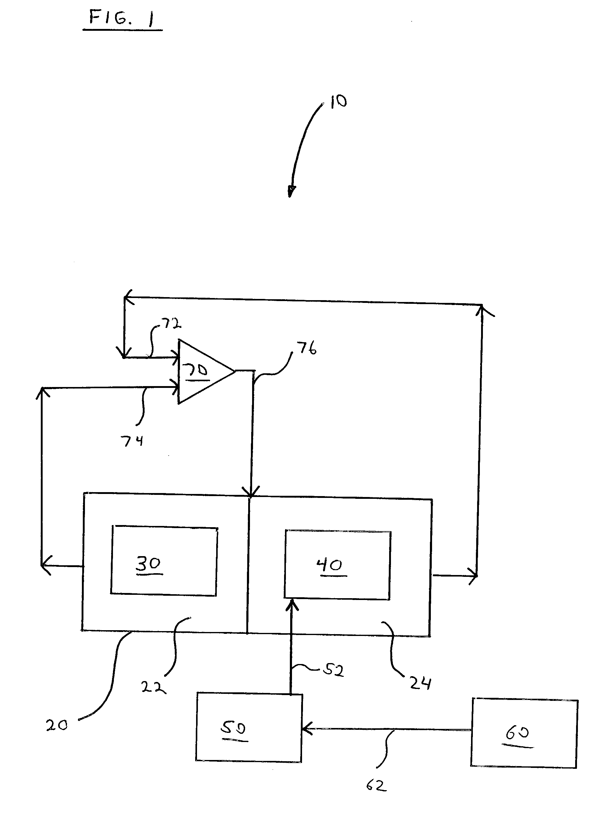
[0026] With reference to FIG. 1, there is shown an exemplary overview of a system 10 for measuring the velocity of a fluid in accordance with the present invention. In general, in certain embodiments, a temperature sensor 60 measures the temperature of a fluid, and transmits the temperature data to controller (or microcontroller) 50. Controller 50 may be any type capable of performing the functions as described herein, as known to those skilled in the art, such as, for example, one supplied by Microchip as part number PIC1GF-76-04 / 50. The system is configured, by way of certain parameters stored at controller 50, such that element (or thermistor) 30 should be maintained at a certain temperature above that of the fluid, as measured by temperature sensor 60. As described herein, element 30 may be a thermi...


PUM


Abstract

A system for measuring the velocity of a fluid can comprise a temperature sensor, for measuring the ambient temperature of the fluid, an RTD placed in the flow path of a fluid, the RTD being included as part of a Wheatstone bridge circuit, a digital potentiometer, the digital potentiometer also being included as part of a Wheatstone bridge circuit, and a controller coupled to the temperature sensor, the RTD and the digital potentiometer. In the system, the controller adjusts the digital potentiometer in response to an ambient fluid temperature signal from the temperature sensor such that the temperature of the RTD remains at a constant differential temperature above the ambient fluid temperature.

Description

[0001] This application claims the benefit of U.S. Provisional Application Serial No. 60 / 387,789, entitled Constant Differential Temperature Mass Flow Sensor With a Variable Wheatstone Bridge Circuit, filed Jun. 12, 2002, the contents of which are incorporated herein by reference.[0002] 1. Field of the Invention[0003] The invention relates generally to the field of fluid velocity measurement and, more particularly, to a method and system for measuring the velocity of fluids by way of hot wire anemometry.[0004] 2. Description of Related Art[0005] Many processes and devices make use of moving fluids. Some examples are heating and ventilating systems that make use of moving air, as well as manufacturing processes that rely on the use and flow of various gasses. Typically, for these processes and / or devices, it is important that the velocity of the fluid be accurately determined. Accordingly, various techniques to determine the velocity of a fluid have been developed.[0006] One such tec...

Claims


Application Information

Patent Timeline
Patent Type & Authority Applications(United States)
IPC IPC(8): G01F1/684G01F1/698
CPCG01F1/698G01F1/684
Inventor COHEN, ADAM J.TANG, JOSH E.THIBODEAU, THOMAS R.
Owner POLAR CONTROLS
Why Eureka
Try Eureka