Magnetic actuator with reduced magnetic flux leakage and haptic sense presenting device

a magnetic actuator and magnetic flux technology, applied in the field of magnetic actuators and haptic sense presenting devices, can solve the problems of insufficient driving force, large leakage of magnetic field from the side to the outside, and inability to provide a yoke on the side of the magnetic actuator,

Inactive Publication Date: 2004-03-25
FUJIFILM BUSINESS INNOVATION CORP
View PDF19 Cites 30 Cited by
  • Summary
  • Abstract
  • Description
  • Claims
  • Application Information

AI Technical Summary

Problems solved by technology

However, the above-described conventional magnetic actuator has the following problems.
However, a yoke cannot be provided on the side of the magnetic actuator, because the members avoid interfering with one another when the plane coil 12 is moved, which means that leakage of the magnetic field from the side to the outside is larger than that from the upper and the lower parts thereof.
Moreover, when the plane coil 12 moves farther away from the center of the magnetic actuator, it is more susceptible to the influence of the reduction of the magnetic field due to the leakage of the magnetic flux from the side of the magnetic actuator, and a sufficient driving force cannot be obtained.
Specifically, when the plane coil 12 is moved to the ends of the magnetic actuator in the X and the Y directions, a problem is caused that a driving force is generated substantially in the vertical direction for all the plane coils 12.

Method used


Image

  • Magnetic actuator with reduced magnetic flux leakage and haptic sense presenting device
  • Magnetic actuator with reduced magnetic flux leakage and haptic sense presenting device
  • Magnetic actuator with reduced magnetic flux leakage and haptic sense presenting device

Examples


second embodiment

[0091] (Second Embodiment)

[0092] A second embodiment of a magnetic actuator according to the present invention will now be described.

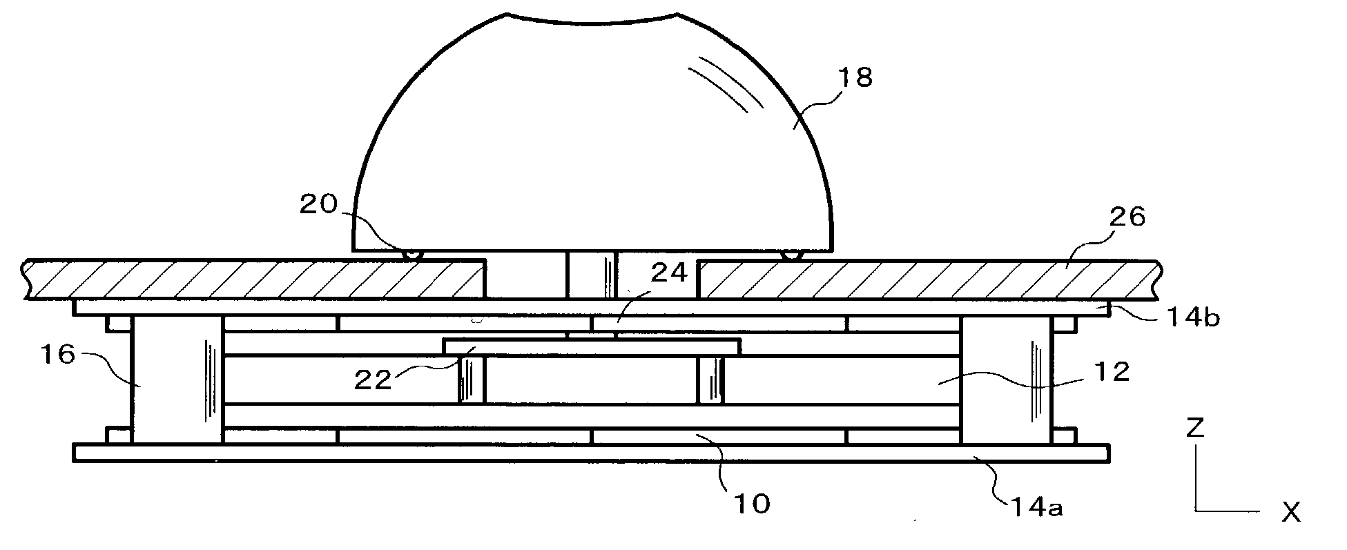
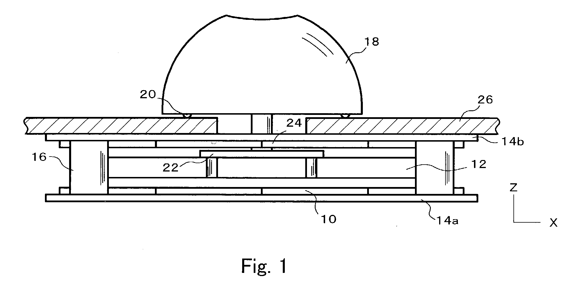
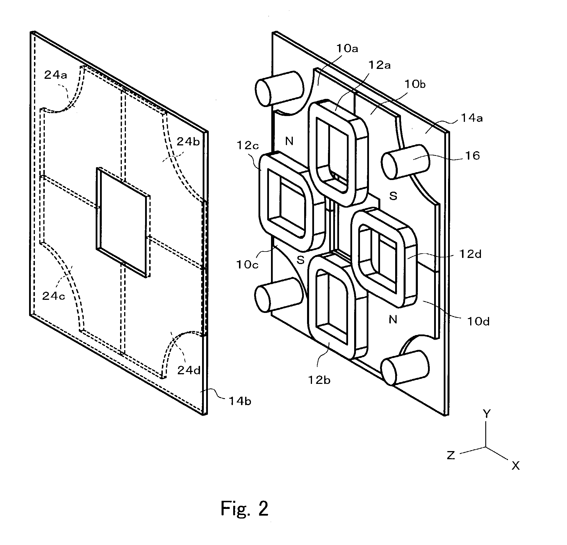
[0093] As shown in FIGS. 8 and 9, a magnetic actuator 1 is provided with a first yoke plate 14a and a second yoke plate 14b. The first yoke plate 14a and the second yoke plate 14b are formed with a magnetic substance. The first yoke plate 14a has the shape of a substantially square flat plate, and has a first surface 30a and a second surface 30b which is the opposite surface of the first surface 30a. The second yoke plate 14b has the shape of a substantially square flat plate with four corners obliquely cut off. The second yoke plate 14b has a third surface 40a and a fourth surface 40b which is the opposite surface of the third surface 40a. The reason why the four corners of the second yoke plate 14b are cut off is to prevent interference at the time of mounting. The first yoke plate 14a and the second yoke plate 14b are provided at positions substanti...

example

[0114] Here, an example of a magnetic actuator according to the present invention will be described. The example is that of the second embodiment described above. In the example, the height d.sub.3 of the magnetic shielding units 31 to 34 is varied by one quarter of the thickness of the magnets 10a to 10d until the height d.sub.3 becomes equal to the thickness of the magnets 10a to 10d, and the magnetic flux leaked to the outside of the magnetic actuator is measured. There, the leakage of the magnetic flux at a position 5 mm apart from the side surface of the magnetic actuator is evaluated.

[0115] FIG. 15 is a graph evaluating the leakage of the magnetic flux from a magnetic actuator. The graph shown in FIG. 15 represents, on the horizontal axis, the ratio in percentage of the height d.sub.3 of the magnetic shielding units 31 to 34 relative to the thickness of the magnets 10a to 10d. The vertical axis of the graph represents the maximum value of the leakage of the magnetic flux at a ...


PUM


Abstract

A magnetic actuator, comprising a magnet, mutually opposite magnetic poles thereof being arranged opposing each other, and a coil, at least one portion thereof being inserted between the corresponding magnetic poles, wherein a driving force for the coil is generated by applying an electric current to the coil in a magnetic field generated by the magnet.

Description

[0001] 1. Field of the Invention[0002] The present invention relates to a magnetic actuator and a haptic sense presenting device which enable reduced leakage of magnetic flux to the outside and can be operated in a stabilized manner.[0003] 2. Description of the Related Art[0004] Recently, a magnetic actuator utilizing an electromagnetic interaction as a driving force has been widely used. For example, with the development of information transfer devices, a means for transmitting information through a haptic sense is needed in addition to a visual sense and an auditory sense, and a haptic sense presenting device incorporating a compact magnetic actuator into a pointing device such as a mouse or the like and capable of giving vibration to a fingertip has been realized.[0005] A haptic sense presenting device incorporating a magnetic actuator has been disclosed in Japanese Patent Laid-Open Publication No. 2000-330688. As shown in FIG. 16A, a haptic sense presenting device is provided wi...

Claims


Application Information

Patent Timeline
Patent Type & Authority Applications(United States)
IPC IPC(8): A61B5/00G06F3/00B06B1/04G06F3/01G06F3/033H02K33/18
CPCG06F3/016Y10T74/20201G06F3/0338G06F3/00
Inventor WATANABE, YOICHITSUKAMOTO, KAZUYUKI
Owner FUJIFILM BUSINESS INNOVATION CORP
Why Eureka
Try Eureka