Pump driven by an electromotor and method for producing a pump of this type

a technology of electromotor and pump, which is applied in the direction of piston pumps, positive displacement liquid engines, magnetic circuit shapes/forms/construction, etc., can solve the problems of reducing the air gap by lessening the thickness of the material, affecting the efficiency of a split pot motor of this kind, and reducing the air gap. , the risk of mechanical instabilities

Inactive Publication Date: 2004-04-01
ROBERT BOSCH GMBH
View PDF23 Cites 91 Cited by
  • Summary
  • Abstract
  • Description
  • Claims
  • Application Information

AI Technical Summary

Problems solved by technology

One disadvantage of the pump-motor unit described in EP-0 778 649 B1 and of all comparable motor pumps is the existing air gap between the stator and the rotor of the electric motor, which adversely affects the efficiency of a split tube motor of this kind.
Reducing the air gap by lessening the thickness of the material of the split pot has the risk of mechanical instabilities of the split pot.
This can cause premature failure of the pump.
Cooling the power electronics of the control motor by means of an additional passive radiator, as proposed in EP-0 778 649 B1-besides requiring one additional split pot increases the complexity of such a pump.
Once again, the complex assembly and sealing of the additional split pot is a disadvantage.

Method used


Image

  • Pump driven by an electromotor and method for producing a pump of this type
  • Pump driven by an electromotor and method for producing a pump of this type
  • Pump driven by an electromotor and method for producing a pump of this type

Examples


Embodiment Construction

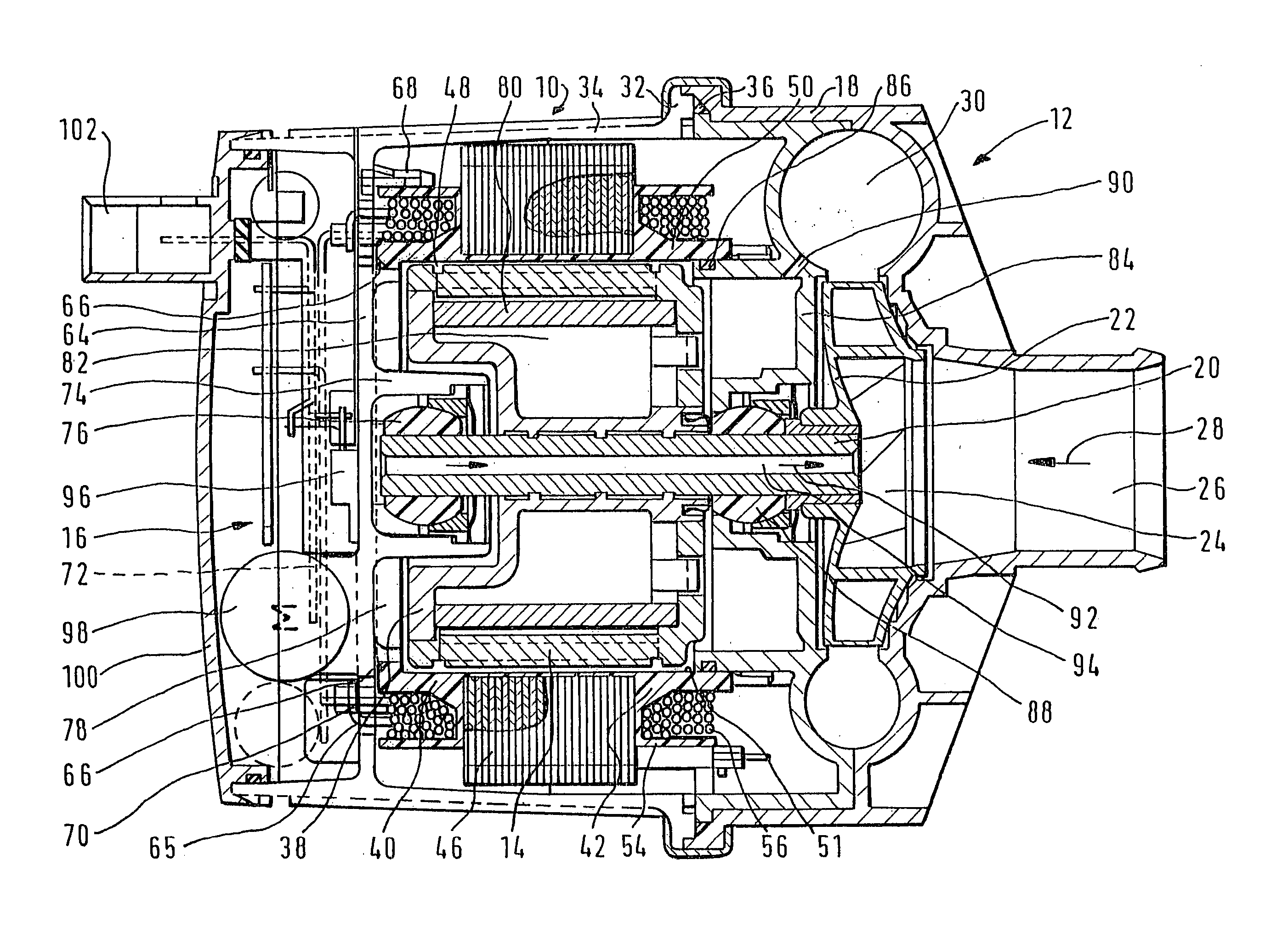
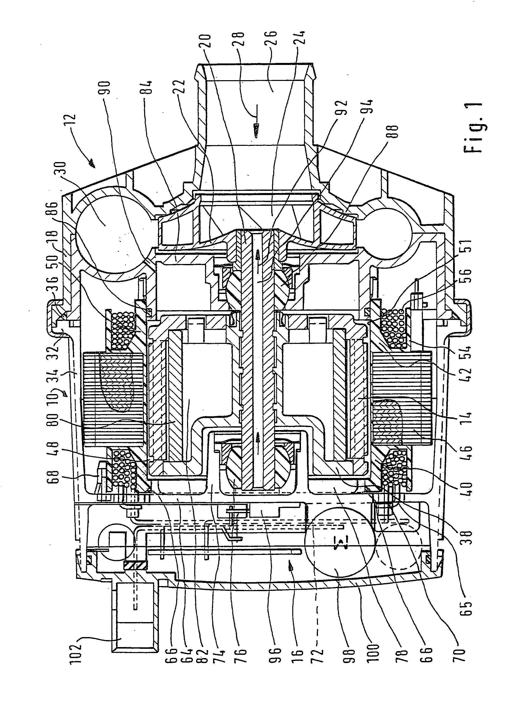
[0023] The exemplary embodiment, shown in longitudinal section in FIG. 1, of an electric-motor-driven pump 10 of the invention comprises a pump head 12, which is driven by a brushless, electronically commutated electric motor 14, and a switch mechanism 16 for controlling the electric motor 14.

[0024] The pump head 12 has a pump housing 18, in which an impeller 22, secured to a drive shaft 20, is located in a pump chamber 11. The impeller 22 is provided with vanes 24 for transporting and increasing the pressure of a fluid to be recirculated. An opening 26 for aspirating the fluid in the direction of the arrow 28 leads into the pump housing 18. The pump housing also has an outlet opening 30, not completely shown in FIG. 1, on the compression side of the pump. The intake opening 26 discharges at the vanes 24 of the impeller 22 of the pump 10. In the exemplary embodiment of the motor pump 10 of the invention shown, the pump housing 18 is connected via a flange 32 to the motor housing 34 ...


PUM


Abstract

The invention relates to a pump (10), having a pump head (12), which has a pump chamber (11), and having an electric motor (14), which drives the pump head (12) and has a stator (40) and a rotor (38), the rotor (38) being connected to the pump head (12) and being disposed in a rotor chamber (82) open toward the pump chamber (11). It is proposed that the stator (40) is disposed radially around the rotor chamber (82), and the rotor chamber (82) is sealed off from the pump chamber (11) by a sealing wall (51) belonging to the stator (40) and by at least one wall (64) of the pump housing (18).

Description

PRIOR ART[0001] The invention is based on a motor pump having a pump head and an electric motor that drives the pump head, as generically defined by the preamble to claim 1, and to a method for producing such a pump, as generically defined by the preamble to claim 20.[0002] Such motor pumps serve to transport or increase the pressure of a fluid and have long been used, for instance as water pumps in heating circuits.[0003] From European Patent EP-0 778 649 B1, a pump-motor unit is known, which acts as a coolant pump of a motor vehicle internal combustion engine. The pump-motor unit described in EP-0 778 649 B1 is a centrifugal pump, which is driven by an electronically commutated direct-current motor. The centrifugal pump and the direct-current motor are connected to one another via a radiator. Fastened between the pump housing and the radiator is a split pot, made of a suitable material, which separates the rotor of the electric motor from the stator. A seal placed between the pump...

Claims


Application Information

Patent Timeline
Patent Type & Authority Applications(United States)
IPC IPC(8): F01P5/04F04C15/00F04D13/06F04D29/00F04D29/58H02K1/18H02K5/00H02K7/14H02K11/00
CPCF04C15/0061F04C15/008F04D13/064F04D13/0626F04D29/588F04D13/0686F04D29/5813F04D13/06
Inventor WEIGOLD, THOMASZIERER, GERALDPFETZER, JOHANNESRIEHL, GUENTHERHENSCHEL, MATTHIASSCHMITZ, MATTHIASROCKLAGE, GERTAHEIDRICH, TORSTENMELZER, FRANKLINDE, HANSJUERGENNEUMANN, UWEREHKLAU, ANDREAS
Owner ROBERT BOSCH GMBH
Why Eureka
Try Eureka