
Distributed data transmitter

Inactive Publication Date: 2004-04-15
HONEYWELL FED MFG & TECHNOLOGI
View PDF15 Cites 0 Cited by
  • Summary
  • Abstract
  • Description
  • Claims
  • Application Information

AI Technical Summary

Benefits of technology

[0019] Furthermore, the DTXR's modularity allows for easier interchangeability of its components. Each module can be easily and conveniently removed and replaced without removing other modules. This allows for quickly and efficiently customizing the DTXR's capabilities and performance to particular applications. Thus, whereas prior art transmitters have fixed, inflexible attributes, capabilities, and performance, the DTXR facilitates customization and modification to accommodate a variety of different applications or changing demands in the same application.
[0020] Additionally, the DTXR incorporates digital and microwave technology to provide substantial improvements in flexibility of use by way of a programmable carrier frequency, a variable RF spectrum, a variable data rate, a scalable output power, a customizable efficiency, an adaptable multi-mode modulation, and a customizable bandwidth.
[0021] Additionally, each distinct module or submodule of the DTXR is received in a housing adapted to further enhance modularity and distributability with standardized mechanical and electrical connectors, thereby advantageously allowing for substantially any distributed or co-located physical arrangement of the housings, including stacking, end-to-end, side-to-side, or any combination thereof.

Problems solved by technology

Unfortunately, where the system was not initially designed to accommodate the transmitter, it can often be very difficult or impossible to integrate the transmitter into the available space.
This is a particular problem where the transmitter must be enclosed within the system's existing housing, such as, for example, where the system is part of a flight vehicle.
Furthermore, while it may be possible in such situations to undertake a substantial repositioning of the system's components to make space for and otherwise accommodate the transmitter, doing so is likely undesirably or prohibitively costly and time-consuming and may sufficiently change the system so as to undermine the very test meant to be performed.
Thus, the physical characteristics of prior art transmitters are typically inflexible, making the transmitters physically unadaptable and unsuitable for use in a variety of applications or changing conditions.
Unfortunately, the replacement transmitter, if it is of a different shape or size than the replaced transmitter, may not fit within the same space.
Thus, prior art transmitters typically suffer from, for example, a rigid analog technology; limited data throughput; fixed data rates; fixed deviation; fixed spectrum; fixed analog modulation; and fixed power capacity, such that they are typically operatively unadaptable and not suitable for use in a variety of applications or changing conditions.

Method used


Image

  • Distributed data transmitter
  • Distributed data transmitter
  • Distributed data transmitter

Examples


first embodiment

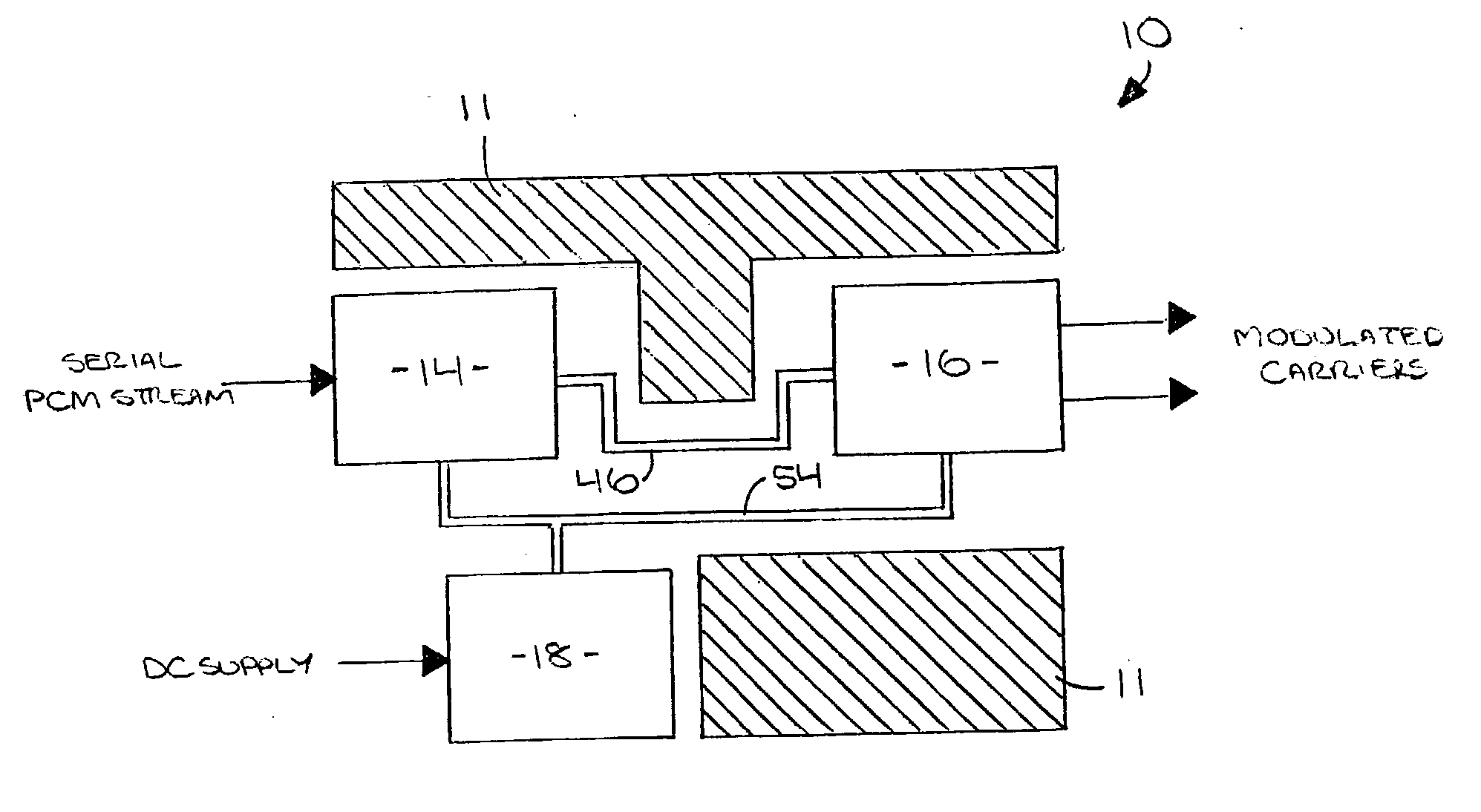
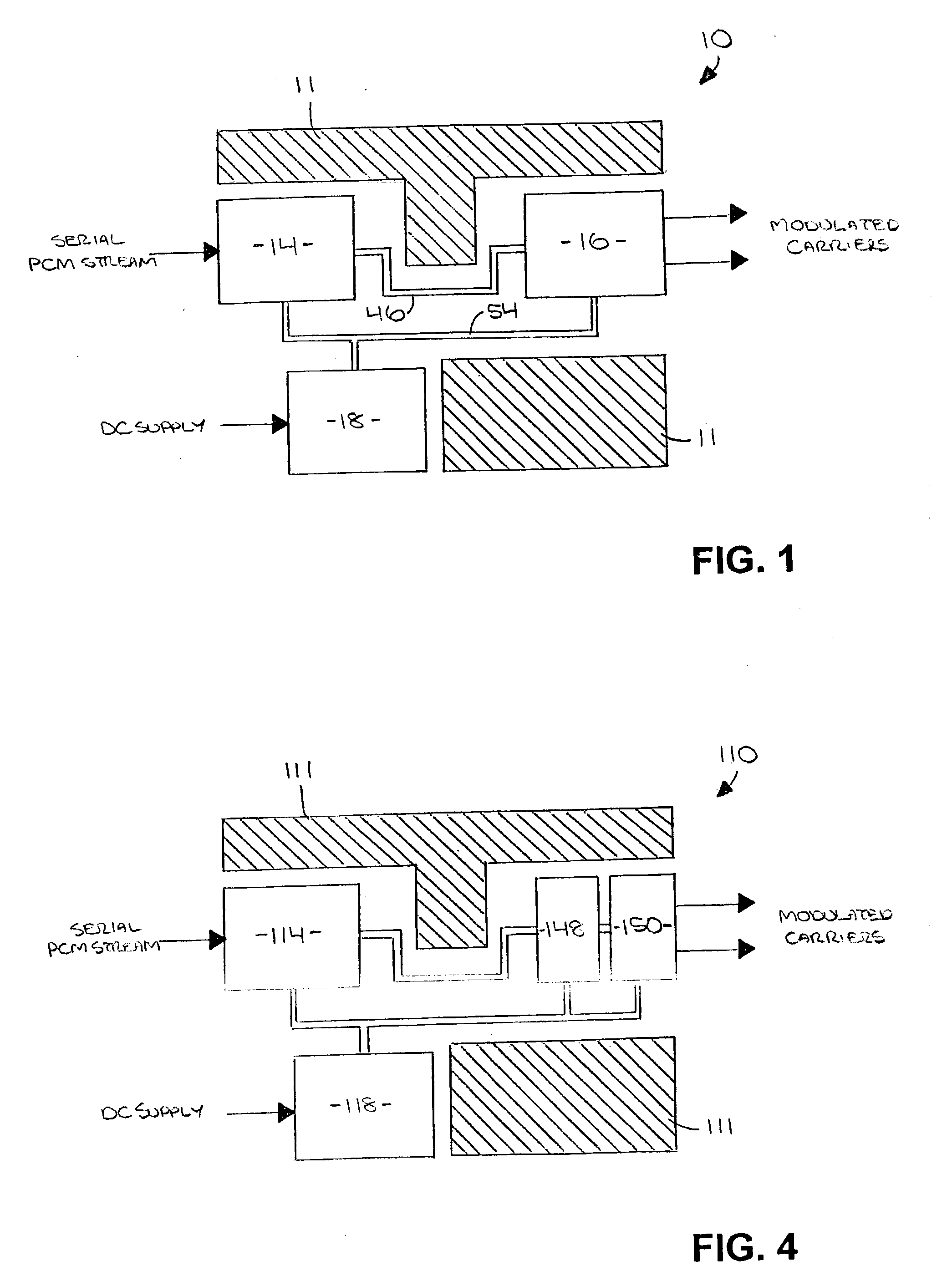
[0024] FIG. 1 is a high level block diagram of a plurality of components of a preferred first embodiment of the DTXR of the present invention;

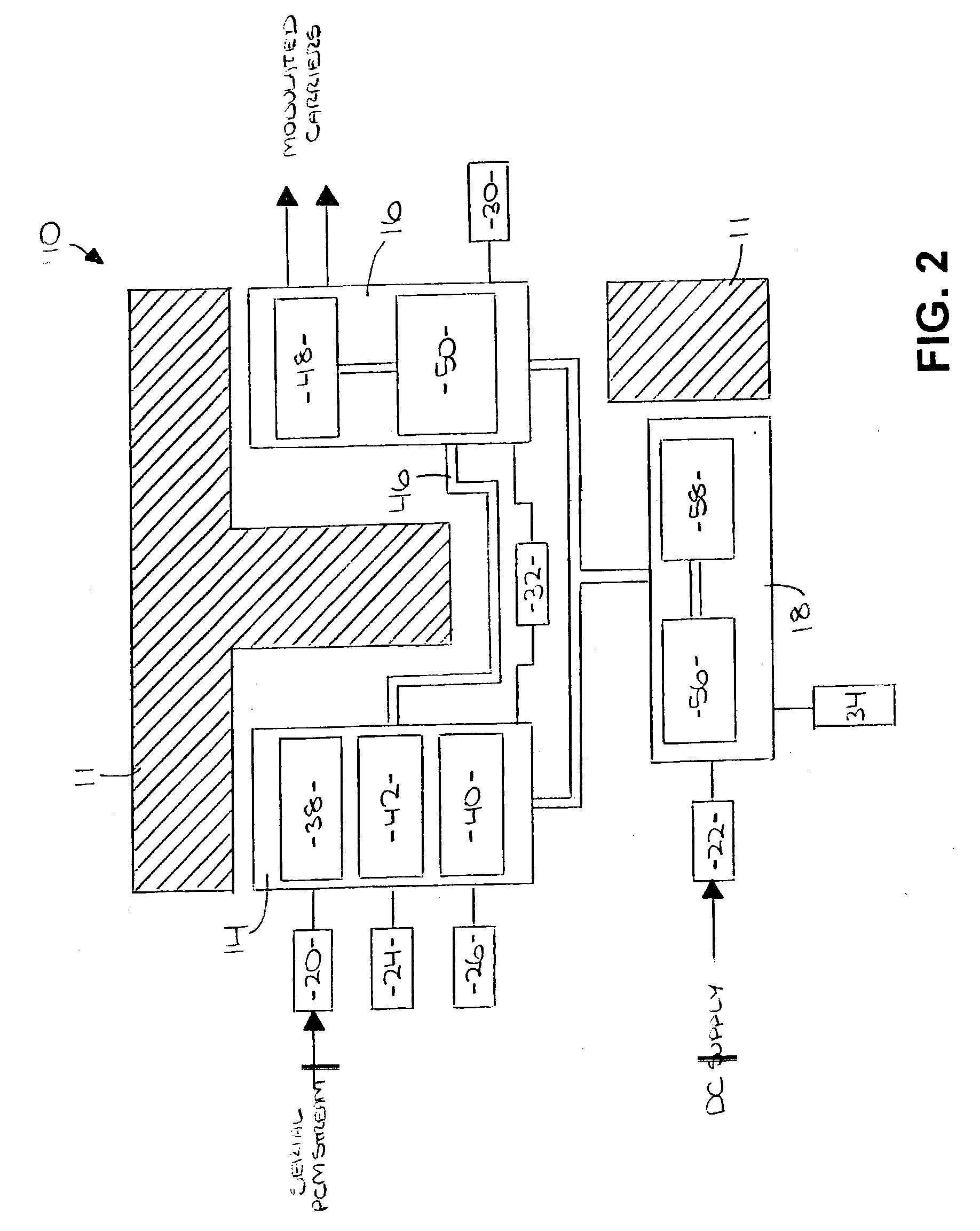
[0025] FIG. 2 is a low level block diagram of the components of the DTXR of FIG. 1;

[0026] FIG. 3 is an exploded isometric view of a preferred embodiment of a housing for enclosing each of the plurality of components of the DTXR of FIG. 1; and

second embodiment

[0027] FIG. 4 is a high level block diagram of a plurality of components of a preferred second embodiment of the DTXR of the present invention.

DETAILED DESCRIPTION OF A PREFERRED EMBODIMENT

[0028] Referring to FIGS. 1 and 2, a distributed data transmitter (DTXR) 10 is shown constructed in accordance with a preferred first embodiment of the present invention. The DTXR 10 is an adaptive data communication microwave transmitter having a distributable architecture of modular components and incorporating both digital and microwave technology to provide substantial improvements in flexibility of use by way of a programmable carrier frequency, a variable RF spectrum, a variable data rate, a scalable output power, an adaptable multi-mode modulation, and a customizable bandwidth. The DTXR 10 has application in, for example, remote data acquisition involving the transmission of telemetry data across a wireless link, wherein the DTXR 10 is integrated into and utilizes available space within a s...


PUM


Abstract

A distributed data transmitter (DTXR) which is an adaptive data communication microwave transmitter having a distributable architecture of modular components, and which incorporates both digital and microwave technology to provide substantial improvements in physical and operational flexibility. The DTXR has application in, for example, remote data acquisition involving the transmission of telemetry data across a wireless link, wherein the DTXR is integrated into and utilizes available space within a system (e.g., a flight vehicle). In a preferred embodiment, the DTXR broadly comprises a plurality of input interfaces; a data modulator; a power amplifier; and a power converter, all of which are modularly separate and distinct so as to be substantially independently physically distributable and positionable throughout the system wherever sufficient space is available.

Description

[0001] The present application is a continuation-in-part and claims priority benefit of a co-pending patent application titled "DISTRIBUTED DATA TRANSMITTER", Serial No. 10 / 271,459, filed Oct. 15, 2002, the content of which is hereby incorporated into the present application by reference.[0003] 1. Field of the Invention[0004] The present invention relates broadly to microwave transmitter architecture and components. More particularly, the present invention concerns an adaptive data communication microwave transmitter having a distributable architecture of modular components, and incorporating both digital and microwave technology to provide substantial improvement in flexibility of use; and has broad application in, for example, the transmission of data across a wireless link.[0005] 2. Description of the Prior Art[0006] It is often desirable to receive telemetry data from, for example, a system under test or otherwise monitored. Such data is typically transmitted using a prior art m...

Claims


Application Information

Patent Timeline
IPC IPC(8): H04B1/04
CPCH04B1/04
Inventor BROWN, KENNETH D.DUNSON, DAVID
Owner HONEYWELL FED MFG & TECHNOLOGI
Learn More