Optical resonant frequency converter

a frequency converter and optical resonant technology, applied in optics, laser details, instruments, etc., can solve the problems of reducing the conversion efficiency level, reducing the conversion efficiency, and inefficient non-resonant conversion for practical use, etc., and achieve the conversion efficiency of frequency converters in accordance with the state of the art. unsatisfactory low

Inactive Publication Date: 2004-04-15
NLG NEW LASER GENERATION
View PDF5 Cites 14 Cited by
  • Summary
  • Abstract
  • Description
  • Claims
  • Application Information

AI Technical Summary

Problems solved by technology

Particularly in the case of non-linear production of continuous UV laser light, resonant frequency doubling in an external resonator plays a significant part as the crystal materials available for that wavelength range have only low non-linear coefficients and therefore non-resonant conversion is too inefficient for practical use.
The divergence of the beam in the crystal, which increases at the same time, reduces however the level of conversion efficiency in crystals which are substantially longer than the waist region (Raleigh length) of the beam.
When using fundamental wave lasers in the power range of between 10 mW and 100 mW which are suitable for building particularly compact UV lasers however the conversion efficiency of a frequency converter in accordance with the state of the art is unsatisfactorily low as that power range still involves a quadratic dependency on the fundamental wave power.
In general terms adverse effects in terms of the output power of a laser with frequency converter occur by virtue of various phenomena discussed hereinafter.
Antireflection coatings are normally only very limitedly effective at angles of incidence above 50.degree. and with s-polarisation.
The reflection losses cannot be reduced under those conditions to a usable value in the range below 1 percent so that the gain in efficiency by virtue of the reduction in the walk-off effect is nullified again by a loss in efficiency due to the higher resonator losses.
The walk-off effect also has a detrimental action on the beam profile of the laser beam produced by frequency doubling.
However, no measures are sp

Method used


Image

  • Optical resonant frequency converter
  • Optical resonant frequency converter
  • Optical resonant frequency converter

Examples


Embodiment Construction

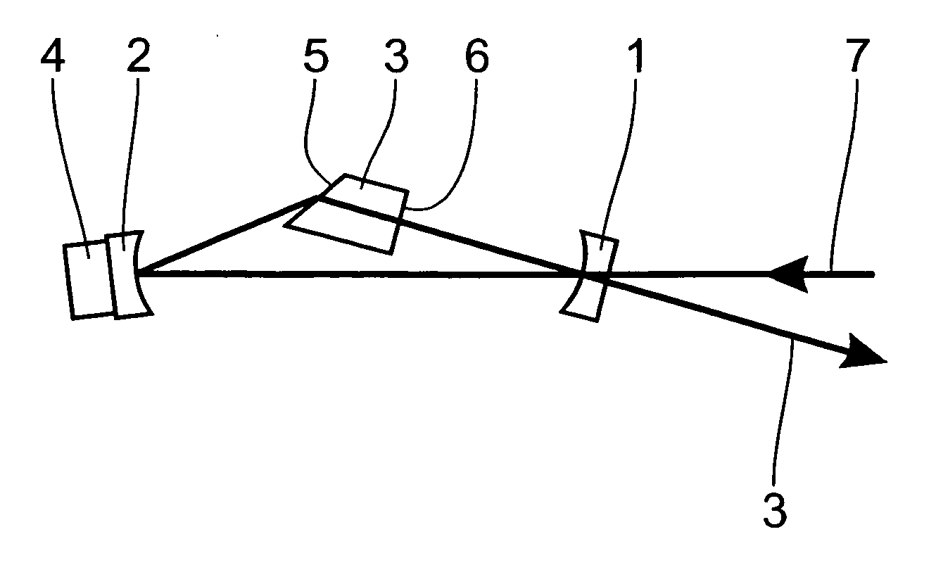
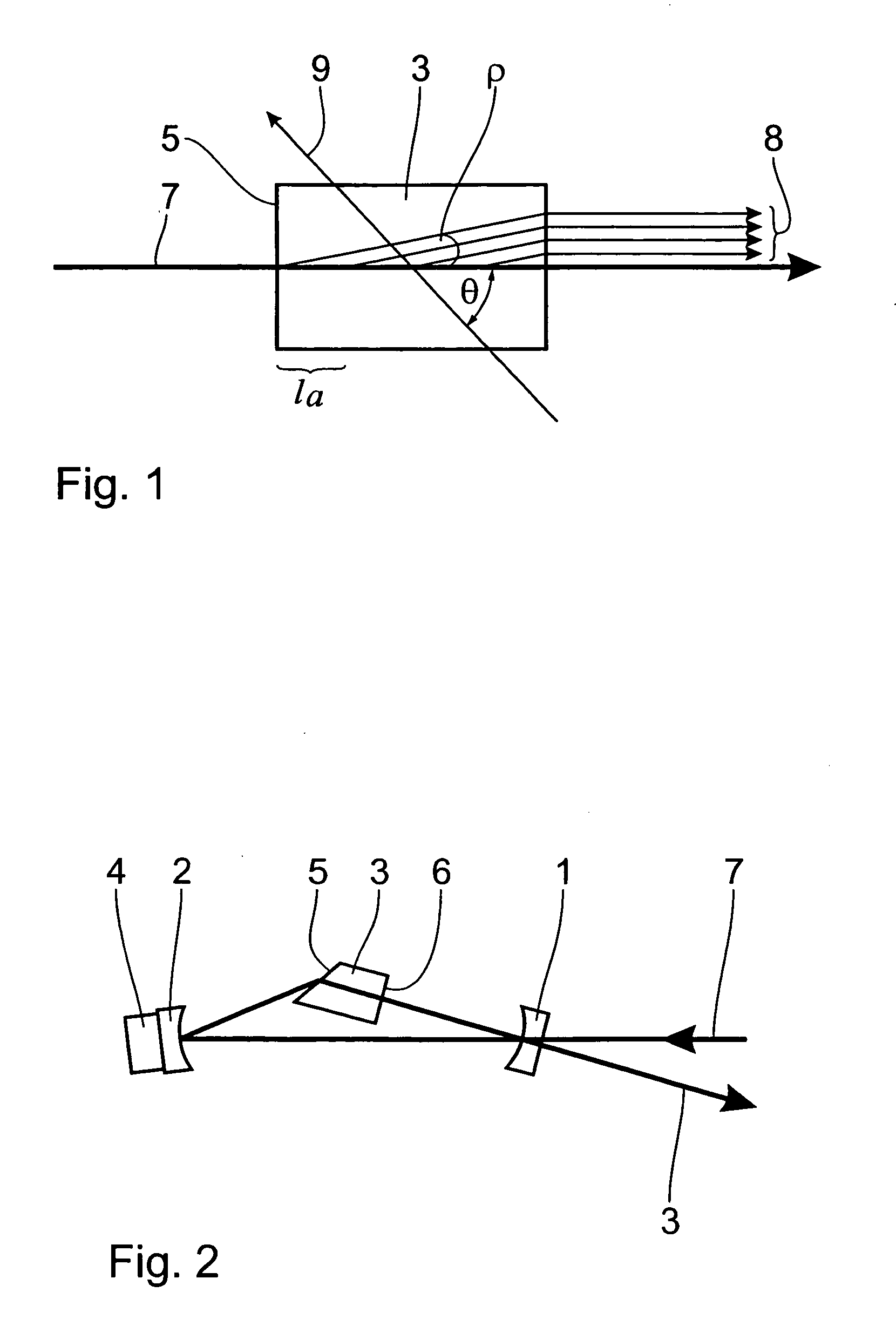
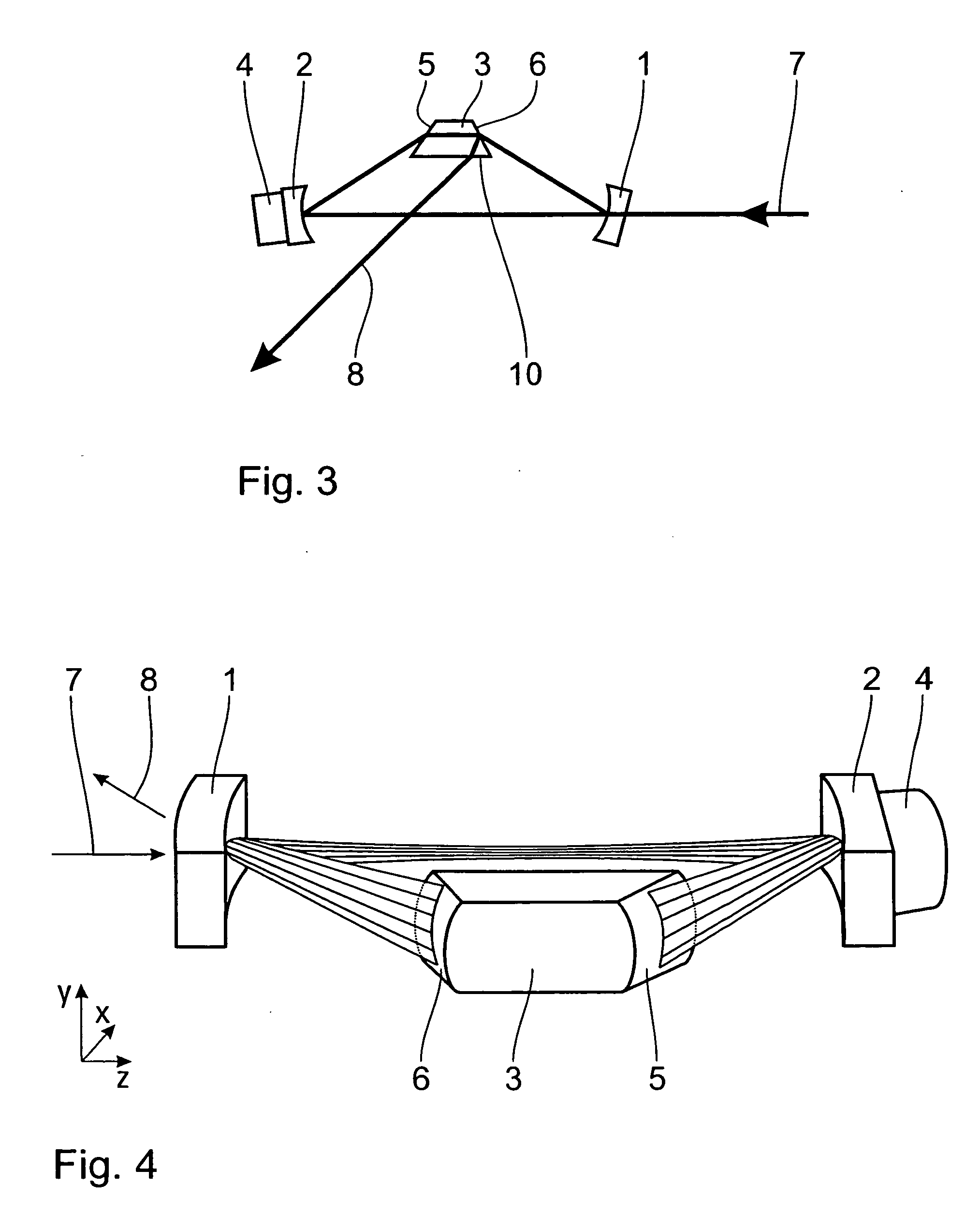
[0057] In the embodiment of FIG. 2 the mirror 1 is used both as the coupling-in mirror for the fundamental wave 7 and also as the coupling-out mirror for the converted beam 8. The mirror 1 is therefore provided with a coating which at the fundamental wavelength has a reflectivity R which is as close as possible to the optimum value R=1-V, wherein V denotes the resonator losses. At the wavelength of the converted beam the coating should have a level of transmission which is as high possible. The resonator mirror 2 is provided with a coating which is as highly reflecting as possible for the fundamental wavelength and is fixed on a piezo element 4 so that, by applying an electrical voltage, the mirror can be moved and thereby the resonator can be tuned to the frequency of the fundamental wave. As the mirror 2 is not used for coupling in the fundamental wave nor for coupling out the converted beam, both the mirror and also the piezo element can be of very small dimensions without an ape...


PUM


Abstract

The invention concerns an optical resonant frequency converter comprising two mirrors and a non-linear crystal in a ring resonator arrangement for converting laser radiation into frequency-doubled radiation. Because of the refractive effect of the prism-shaped, non-linear crystal two mirrors are sufficient to form a ring resonator with a total of three optical elements. A suitable choice of the orientation of the crystal axes in relation to the laser beam direction reduces scatter in the crystal. In one embodiment the entry surface of the crystal is at the Brewster angle while the exit surface is perpendicular to the beam and has an antireflection coating. In another embodiment the converted beam is coupled out through a polarisation beam splitter layer on one of the crystal surfaces. In a further embodiment the crystal surfaces are cylindrically curved. That produces an elliptical beam profile in the crystal, which reduces the walk-off effect.

Description

[0001] The invention concerns an optical resonance frequency converter comprising a ring resonator which includes a first mirror, a second mirror and a non-linear crystal with an entry surface and an exit surface, wherein formed in the ring resonator is a light wave which circulates in a resonator plane and which passes into the non-linear crystal as a first laser beam through the entry surface and issues therefrom again through the exit surface and which is partially converted in the non-linear crystal into a second laser beam which is of a different frequency from the first laser beam. In particular the invention relates to an optical resonant frequency doubler, that is to say a frequency converter which produces a light wave at double the frequency of an incoming light wave.BACKGROUND OF THE ART[0002] An optical resonant frequency converter is used to produce in a particularly efficient manner from a laser beam involving a fundamental wavelength, referred to hereinafter as the fu...

Claims


Application Information

Patent Timeline
IPC IPC(8): G02F1/37
CPCG02F2203/15G02F1/37G02F1/3509
Inventor ZANGER, ECKHARDSALZMANN, MANFRED
Owner NLG NEW LASER GENERATION
Why Eureka
Try Eureka