
Display case assembly system

a technology for assembly systems and display cases, applied in the direction of cabinets, fastening means, kitchen equipment, etc., can solve the problems of unattractive and unfinished appearance, time-consuming and awkward frame assembly,

Inactive Publication Date: 2004-04-22
VIRA INSIGHT
View PDF6 Cites 11 Cited by
  • Summary
  • Abstract
  • Description
  • Claims
  • Application Information

AI Technical Summary

Benefits of technology

[0012] It is yet another object of the present invention to provide such a display case assembly system for which there is no fixed order of assembly, so that the assembly process can start at virtually any assembly step and progress efficiently to completion. In other words, all panels and case frame elements are totally independent from each other in the final assembly of the product, so that each single panel or case frame element can be removed and replaced without interference with any of the other system elements.
[0013] It is finally an object of the present invention to provide such a display case assembly system which produces a display case which is extremely reliable, strong and rigid and which is comparatively inexpensive to manufacture and which saves substantial costs in assembly labor.

Problems solved by technology

A problem with prior structural edge assembly methods has been that frame connectors have been used to connect hollow, tubular frame members, often producing sloppy frame member joints and preventing or making difficult concealed passage of electrical wiring through the hollow frame members, and that frame assembly has been very time consuming and awkward.
The alternative to frame connectors has been ordinary screw fasteners fitted through frame members with the fastener heads exposed, producing an unattractive and unfinished appearance.

Method used


Image

  • Display case assembly system
  • Display case assembly system
  • Display case assembly system

Examples


Embodiment Construction

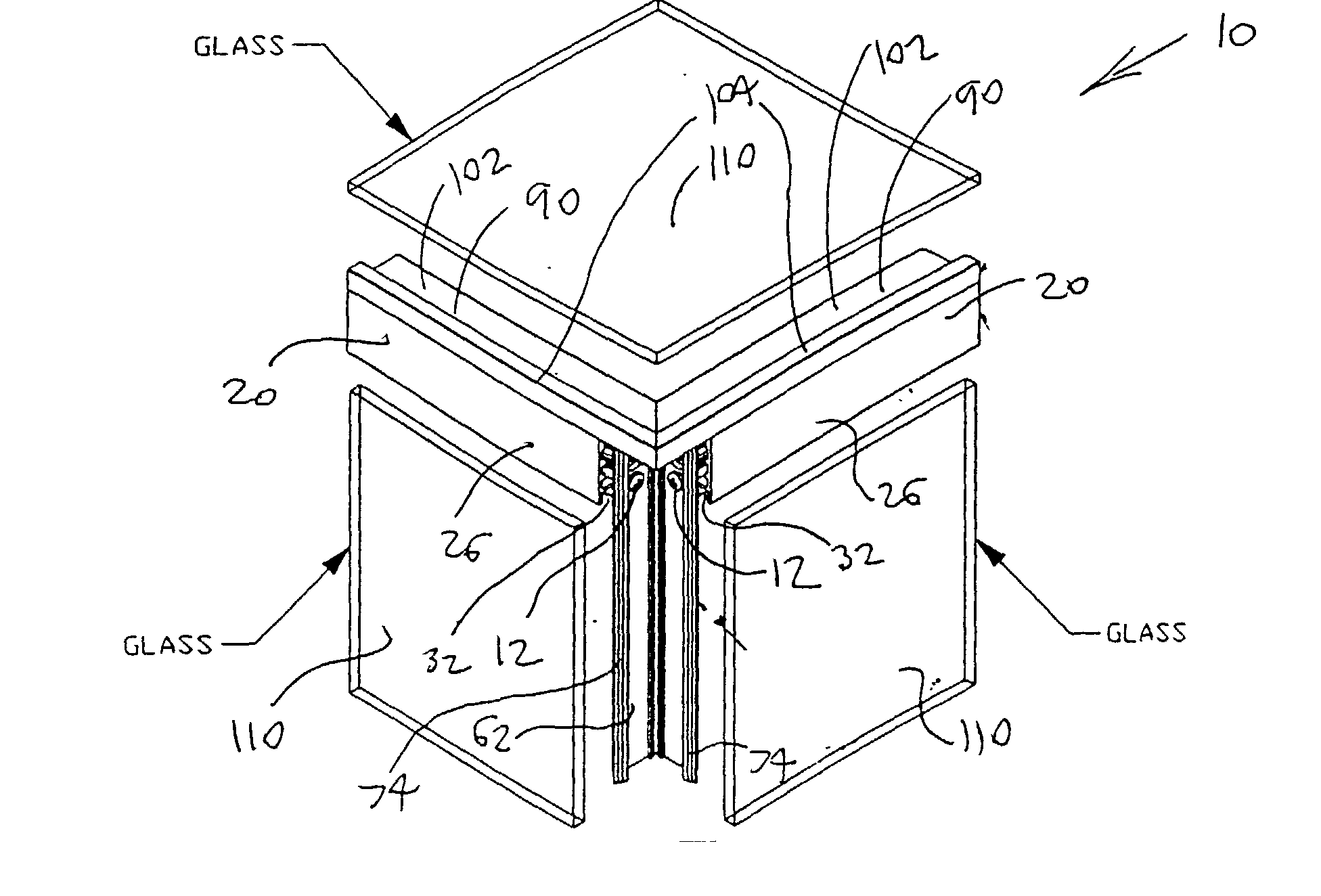
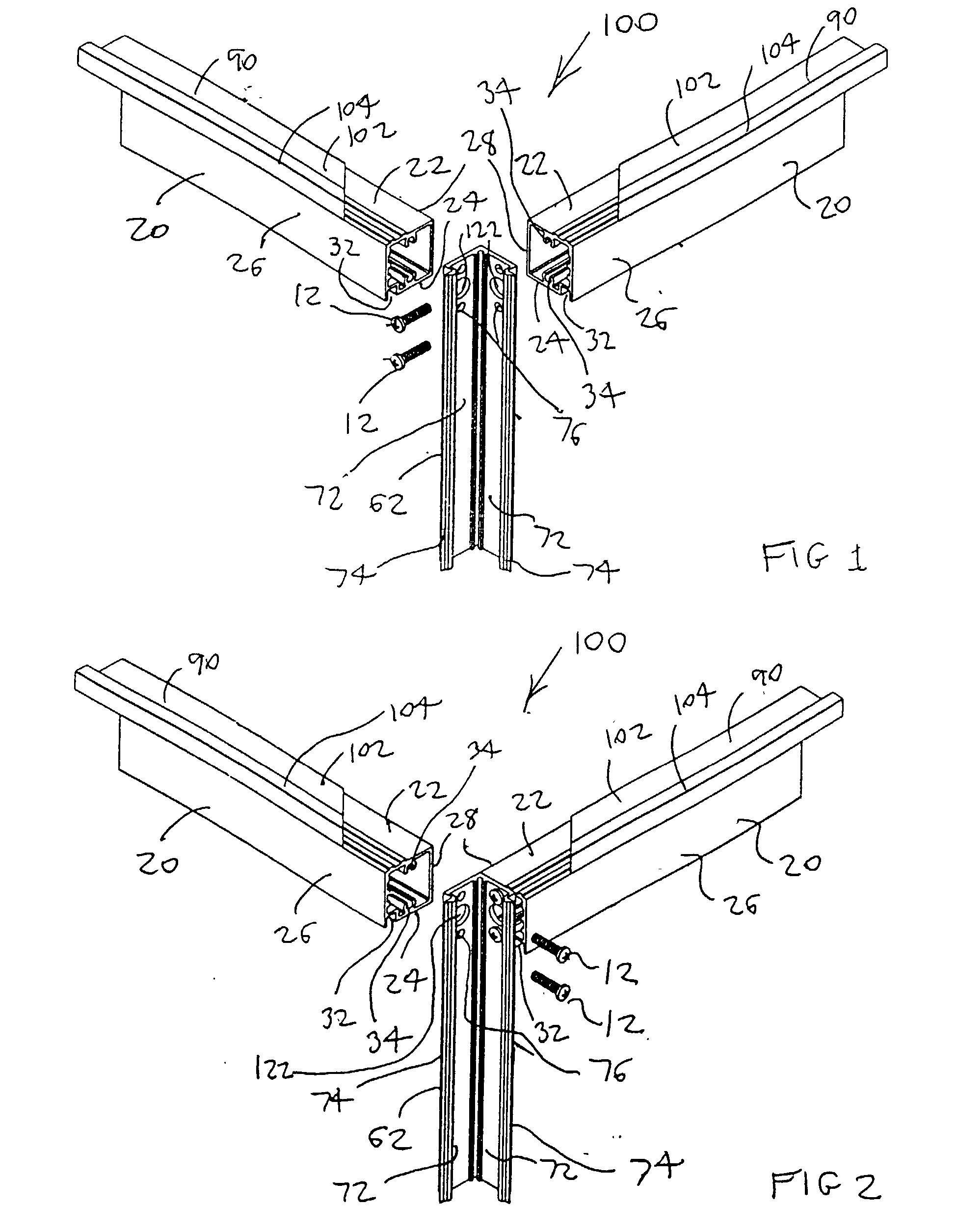
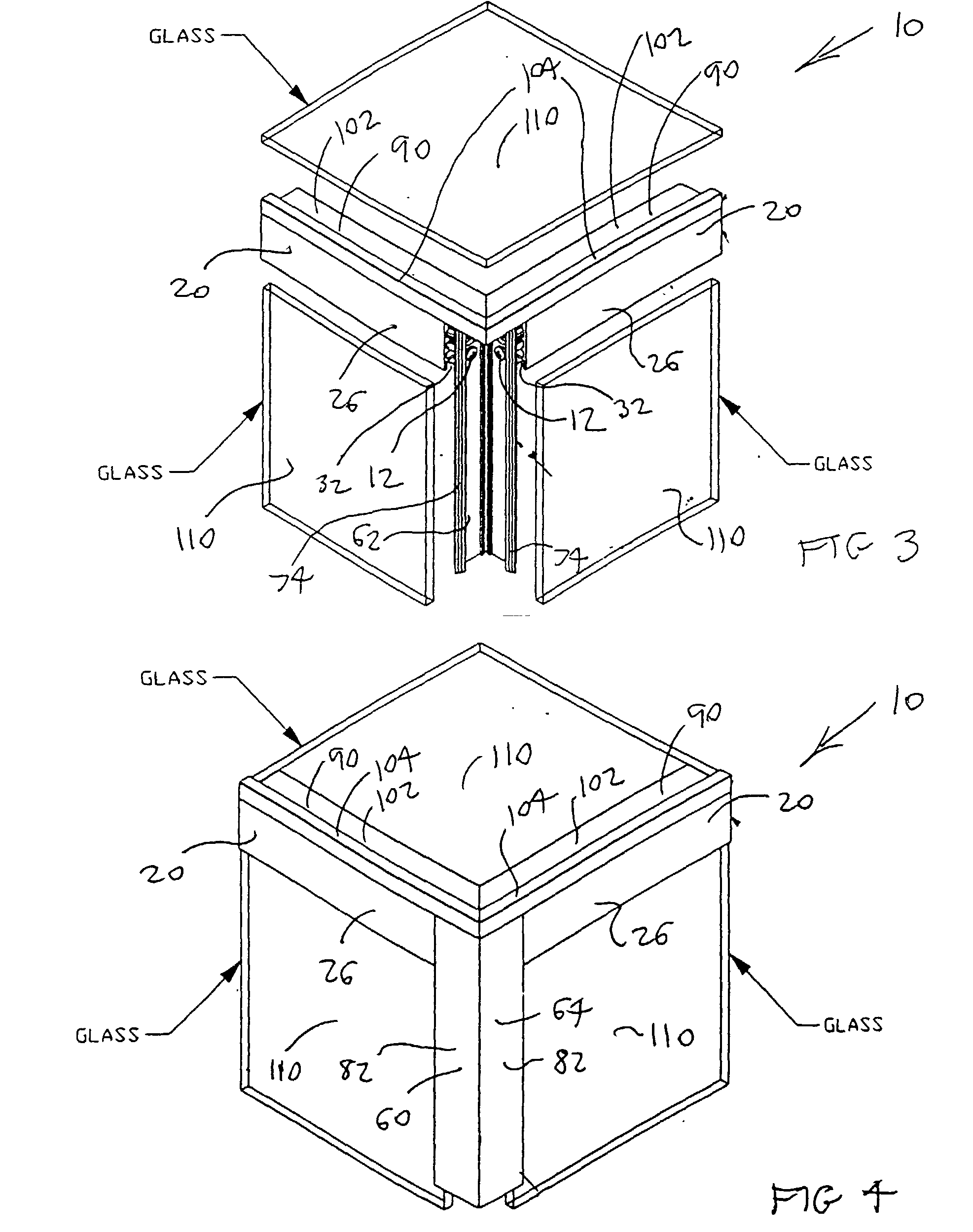
[0053] Referring to FIGS. 1-28, a display case assembly system 10 is disclosed including extruded closed frame tubes 20 and extruded laterally breakable frame tubes 60 which interconnect to form a display case frame 100 and between which opaque and transparent display case panels 110 are fitted and retained, the breakable frame tube 60 opening for insertion of and closing for concealment of frame fasteners 12 and electric wiring 14. The breakable frame tubes 60 each include a mounting section 62 through which fasteners 12 are passed into laterally ends of laterally extending closed frame tubes 20 and a cover section 64 which snap engages laterally to the mounting section 62 to form a composite tube concealing the fasteners 12 and any fixture wiring 14. A panel engaging profile slat 90 is secured to a longitudinal slat mounting face 92 of each closed frame tube 20 with a profile slat engaging structure, and has the dual function of retaining a display case panel 110 and of extending ...


PUM


Abstract

A display case assembly system includes several closed frame tubes, each closed frame tube including two closed frame tube longitudinal ends, at least one closed frame tube longitudinal end including a fastener receiving structure; several laterally breakable frame tubes, each breakable frame tube including a breakable frame tube mounting section having a fastener port; at least one fastener fitted through the fastener port in one of the mounting section and into one of the fastener receiving structures in one of the closed frame tube longitudinal ends, so that at least one breakable frame tube is fastened to one closed frame tube longitudinal end; a breakable frame tube cover section with snap engagement structures for snap engagement with the mounting section to form a composite tube concealing the at least one fastener; and a panel mounted and extending between the closed frame tube and the breakable frame tube.

Description

[0001] 1. Field of the Invention[0002] The present invention relates generally to the field of product retaining structures for containing and displaying products in stores. More specifically the present invention relates to a display case assembly system which is rapidly and easily assembled with conventional threaded fasteners rather than with traditional display case frame connectors, which entirely conceals the fasteners and any lighting fixture electric wiring, and which produces a display case with a neatly finished appearance, thereby solving long term industry problems with elegant simplicity.[0003] The system includes several extruded closed frame tubes and several extruded laterally breakable frame tubes, which interconnect to form a display case frame and between which opaque and transparent panels are fitted and retained, the breakable frame tubes each including a mounting section through which fasteners are passed into longitudinal ends of perpendicular closed frame tub...

Claims


Application Information

Patent Timeline
IPC IPC(8): A47F3/00
CPCA47F3/004A47F3/001
Inventor LATCHINIAN, JIM S.
Owner VIRA INSIGHT
Learn More