
Image processing apparatus and image processing method

a technology of image processing and image processing, applied in the field of image processing apparatus and image processing method, can solve the problems of color shift, data size increase, data transfer time and processing time becoming longer,

Inactive Publication Date: 2004-04-29
FUJIFILM BUSINESS INNOVATION CORP
View PDF8 Cites 25 Cited by
  • Summary
  • Abstract
  • Description
  • Claims
  • Application Information

AI Technical Summary

Problems solved by technology

When a plate misalignment occurs in the printing process using a press plate, there are cases that color shift occurs in a border or the like of an image.
When a spot color is included, there is the possibility that the data size further increases.
Consequently, data transfer time and processing time become longer.
Those proposals however are not related to a method of easily improving transfer time and processing time.
Consequently, even if In-RIP separation is used and a spot color is designated for an image (object) the image is processed as an object expressed in CMYK, so that overprint of the spot color cannot be reproduced accurately.
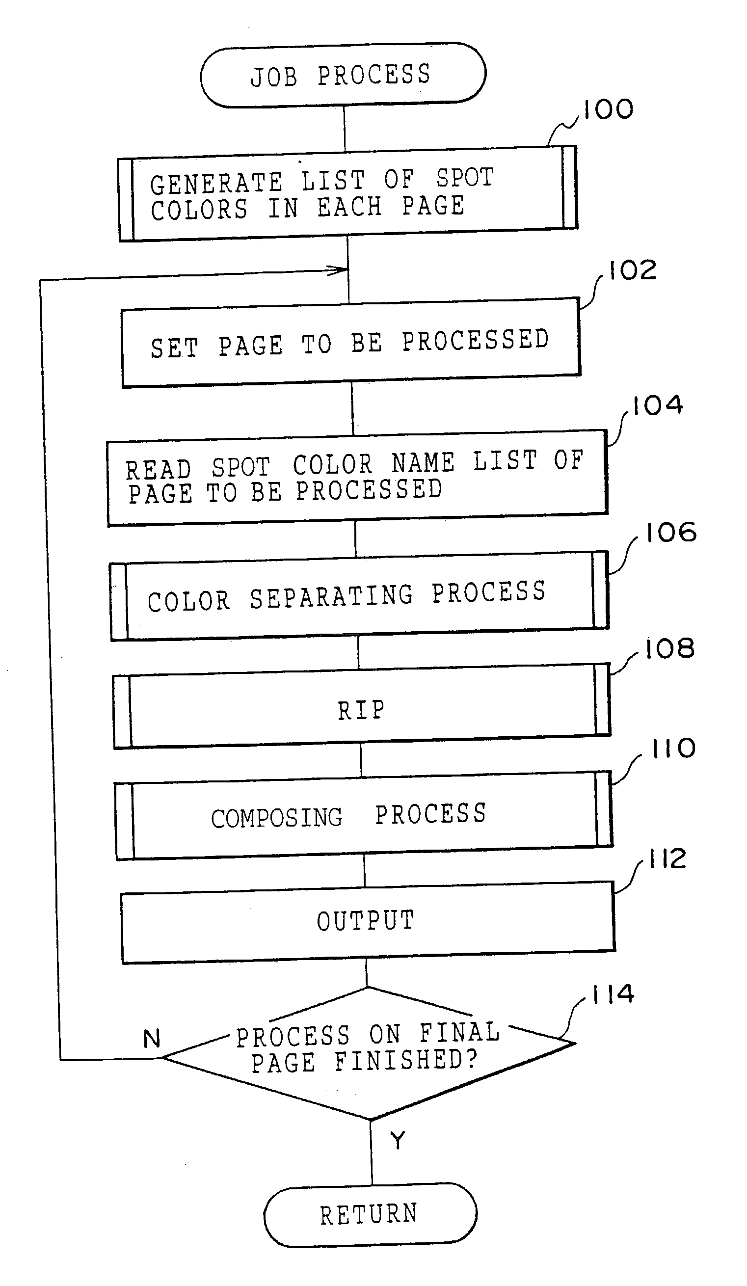
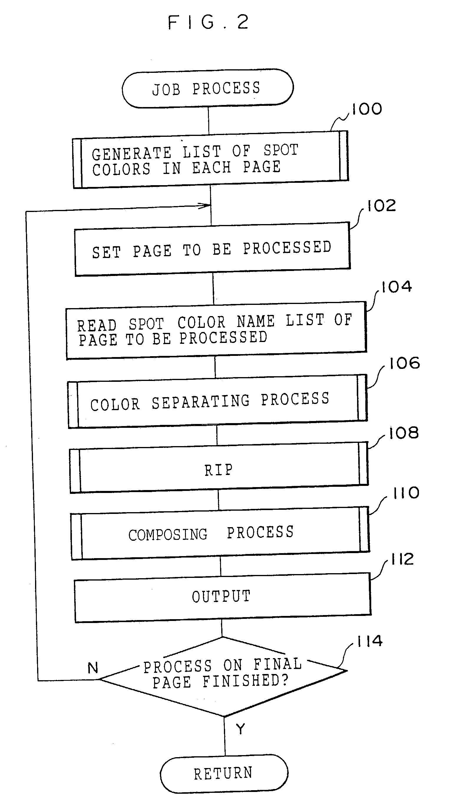
That is, even when a spot color is set in a composite output, the spot color name cannot be known prior to the image processing, so that it is difficult to separate an image into the spot color.
As described above, even when In-RIP separation is used, if a spot color is designated, an image is processed as an image (object) expressed in CMYK and it causes a problem such that an overprint of an object of a spot color cannot be accurately reproduced.

Method used


Image

  • Image processing apparatus and image processing method
  • Image processing apparatus and image processing method
  • Image processing apparatus and image processing method

Examples


first embodiment

[0048] First Embodiment

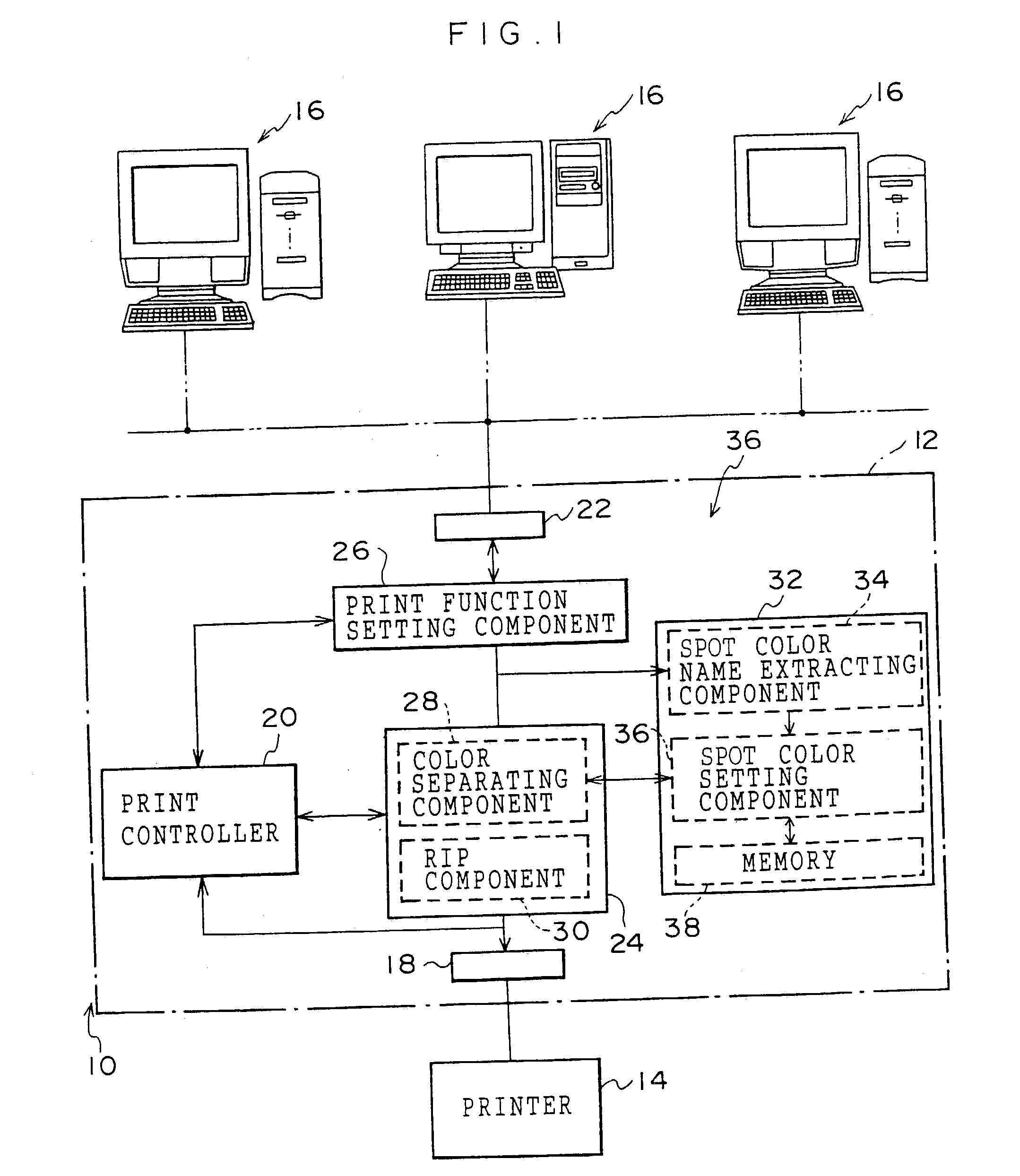
[0049] FIG. 1 shows a schematic configuration of a print system 10 applied to a first embodiment.

[0050] The print system 10 has an image processing apparatus 12 constructed by, for example, adding a PCI board having a predetermined function to a personal computer (PC) of a general configuration. To the image processing apparatus 12, a printer 14 as a printout apparatus is connected, so that an image processed by the image processing apparatus 12 can be printed.

[0051] Further, to the image processing apparatus 12, image processing terminals such as a personal computer and a workstation are connected as client terminals 16. Each of the client terminals 16 can be used for DTP of performing image processes such as generation, processing, editing, and the like of an image by using various applications. The image processing apparatus 12 performs a printing process on the basis of an image drawing command which is input from any of the client terminals 16.

[0052] That...

second embodiment

[0105] Second Embodiment

[0106] A second embodiment of the invention will now be described. The basic configuration of the second embodiment is the same as that of the first embodiment. In the second embodiment, components similar to those of the first embodiment are designated by the same reference numerals and the description will not be repeated.

[0107] FIG. 5 shows the schematic configuration of a print system 50 applied to the second embodiment. The print system 50 applied to the second embodiment has a print server 52 as an image processing apparatus. The print server 52 has an image processing component 58 formed by a color separating component 54 and an RIP component 56, and a spot color processing component 64 formed by a spot color setting component 60 and a memory 62.

[0108] In the spot color setting component 60, a spot color name is preset. The color separating component 54 performs a color separating process on a page layout. At this time, when a spot color name is extrac...


PUM


Abstract

In a print server, when page setting is made, a spot color name is extracted from a comment in an image drawing command and image data or a code of a job on a page (page layout) unit basis and a list for a spot color name of each page is generated. After that, a color separating process and an RIP are performed on the page unit basis, raster data of each of colors C, M, Y, and K and corresponding raster data of a spot color name is generated, after that, on the basis of CMYK values designated by the spot color name, the raster data of the spot color is composed with the raster data of each of the colors C, M, Y, and K, and the resultant is output. In such a manner, an overprint of an object designated in a spot color can be reproduced accurately.

Description

[0001] 1. Field of the Invention[0002] The present invention relates to an image processing apparatus and image processing method for image processing an image such that a printout apparatus prints out the image corresponding to image data generated by various applications. More particularly, the invention relates to an image processing apparatus and method for image processing image data for printing, such that a printout apparatus prints the image data using a printing plate.[0003] 2. Description of the Related Art[0004] As digitization in the field of a printing process, DTP (Desktop Publishing) is penetrating. In the DTP, a page layout is generated by generating, processing and / or editing an image by using various applications on a processing device such as a personal computer or workstation. A film used for exposing a printing plate is generated on the basis of the page layout (image setter or RIP for plate), or a printing plate is generated by writing data directly to a printi...

Claims


Application Information

Patent Timeline
Patent Type & Authority Applications(United States)
IPC IPC(8): B41J5/30B41J2/525G06T1/00H04N1/00H04N1/46H04N1/48H04N1/50H04N1/60H04N1/62
CPCH04N1/00204H04N1/00244H04N1/00326H04N2201/0082H04N2201/0046H04N2201/0068H04N1/62
Inventor NISHIDE, YASUSHIISHIZUKA, RYUICHIKODAMA, MARI
Owner FUJIFILM BUSINESS INNOVATION CORP
Learn More