Discharge lamp lighting device
a technology of lighting device and discharge lamp, which is applied in the direction of lighting and heating apparatus, instruments, process and machine control, etc., can solve the problems of inability to reduce the size of the transformer in the dc/dc converter, and the inability to reduce the size of the dc/dc converter, so as to reduce the electric power output, high electric power, and the effect of electric power outpu
- Summary
- Abstract
- Description
- Claims
- Application Information
AI Technical Summary
Benefits of technology
Problems solved by technology
Method used
Image
Examples
embodiment 1
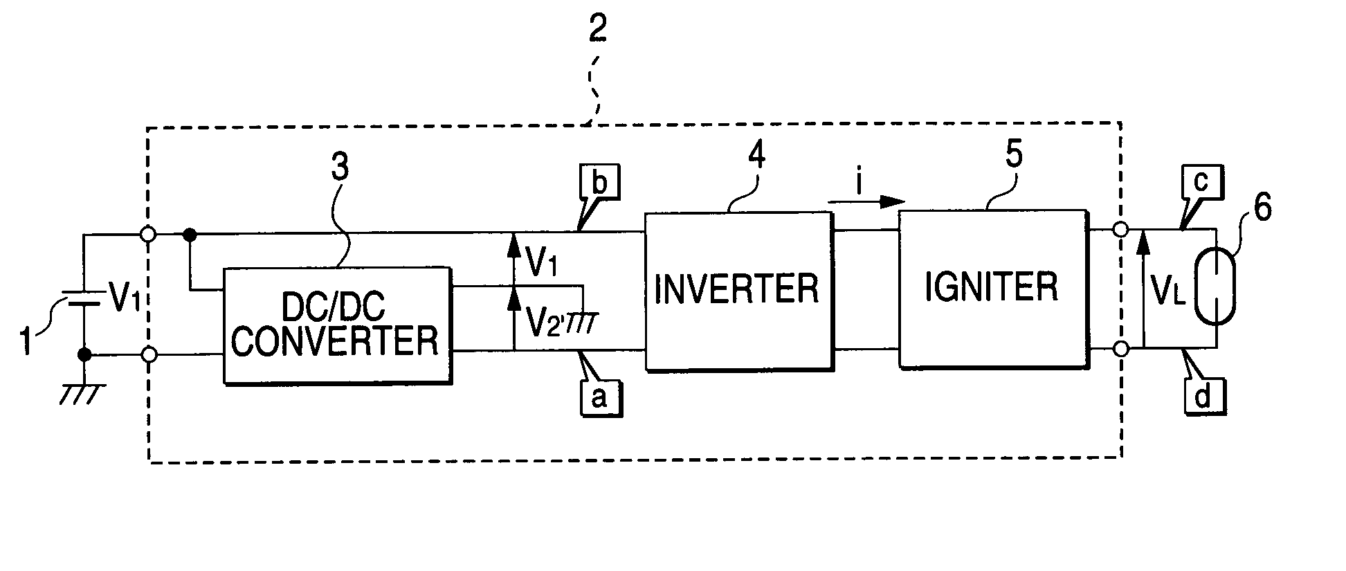
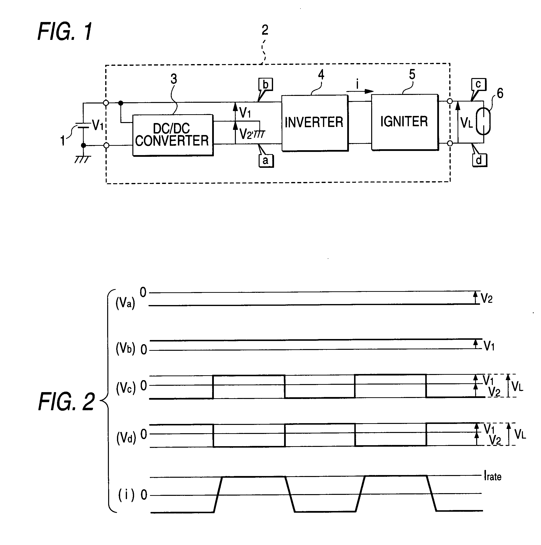
[0027] FIG. 1 is a circuit diagram showing In FIG. 1, the reference numeral 1 designates a DC source such as a car battery; 2, a discharge lamp lighting device; 3, a DC / DC converter (boosting circuit); 4, an inverter (DC-AC conversion circuit); 5, an igniter (lighting starter circuit); and 6, a discharge lamp. Voltages Va, Vb, Vc and Vd shown in FIG. 2 indicate voltages at points a, b, c and d shown in FIG. 1, respectively.
[0028] The DC / DC converter 3 is provided for converting a source voltage of the DC source 1 into a desired DC voltage. The same DC / DC converter as in the related-art example 1 or 2 may be used as the DC / DC converter 3.
[0029] The operation of the circuit shown in FIG. 1 will be described with reference to FIG. 2 which is a time chart for explaining the operation.
[0030] A negative voltage V2 output from the DC / DC converter 3 and a positive voltage V1 of the DC source 1 are input to the inverter 4. The inverter 4 inverts the polarity of the sum Ve of the two voltage...
embodiment 2
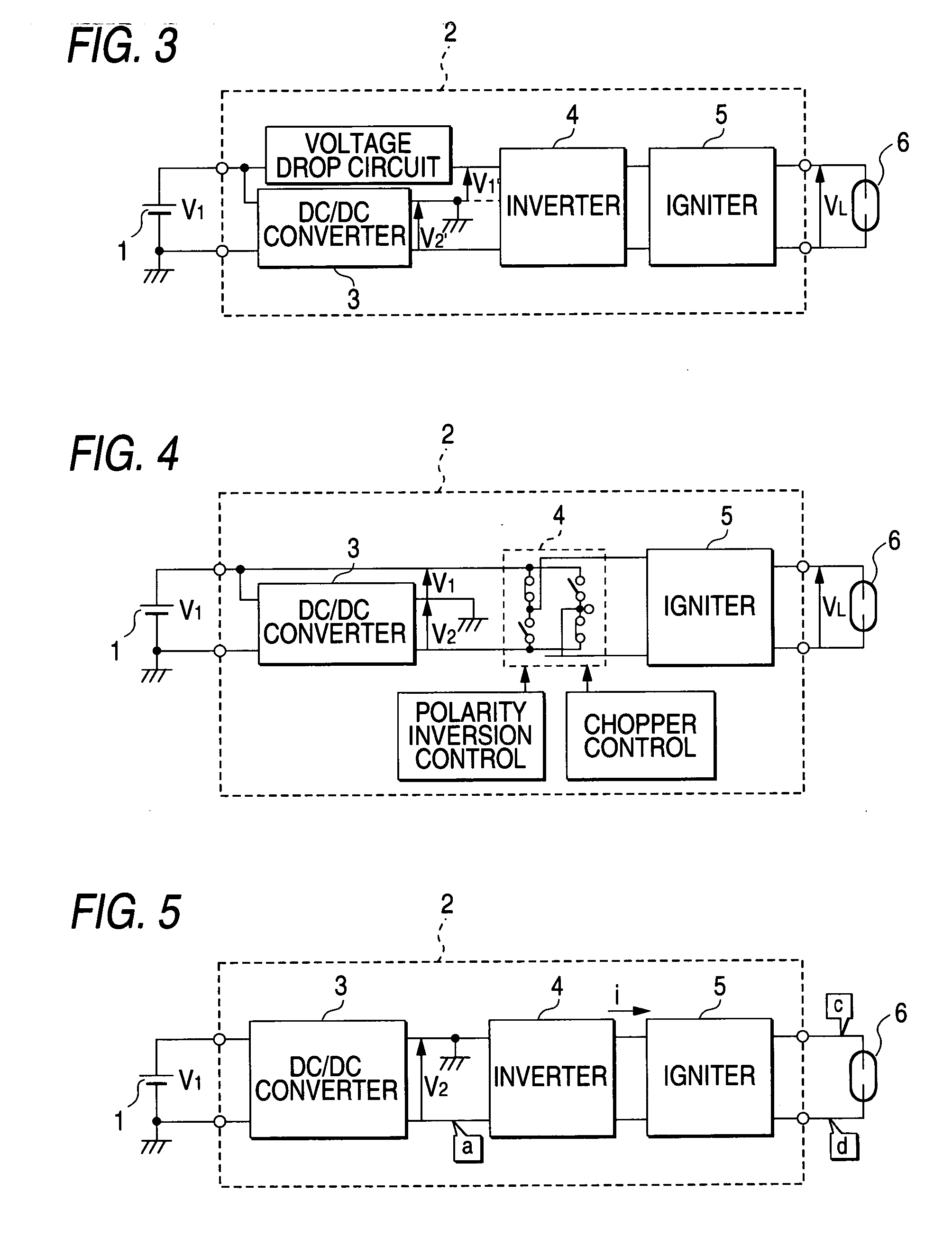
[0035] FIG. 3 shows the case where a negative voltage V2 output from the DC / DC converter 3 and a voltage obtained by dropping a positive voltage V1 of the DC source 1 are superposed on each other. As a result, the discharge lamp can be operated even in the case where the discharge lamp voltage is lower than the positive voltage V1 of the DC source 1. When, for example, the voltage of the DC source is 42 V, the voltage of the discharge lamp is apt to be lower than the voltage of the DC source. Accordingly, the effect due to the provision of the voltage drop circuit is large.
embodiment 3
[0036] FIG. 4 shows the case where a chopper function is given to the inverter 4 so that the output voltage can be dropped. As a result, the discharge lamp can be operated by the application of the inverter even in the case where the discharge lamp voltage is lower than the positive voltage V1 of the DC source 1.
[0037] In the discharge lamp lighting device according to the invention, the discharge lamp is supplied with electric power of a negative voltage boosted by the DC / DC converter and electric power of a positive voltage given from the DC source, so that the electric power capacity of the DC / DC converter can be reduced.
[0038] Furthermore, because electric power of a positive voltage can be given from the DC source through the voltage drop circuit, the discharge lamp can be lighted stably even in the case where the voltage of the discharge lamp is lower than the voltage of the DC source.
[0039] Furthermore, because the voltage drop circuit can be formed by using an inverter, the ...
PUM
 Abstract
Description
Claims
Application Information
 - R&D
- Intellectual Property
- Life Sciences
- Materials
- Tech Scout
- Unparalleled Data Quality
- Higher Quality Content
- 60% Fewer Hallucinations
Browse by: Latest US Patents, China's latest patents, Technical Efficacy Thesaurus, Application Domain, Technology Topic, Popular Technical Reports.
© 2025 PatSnap. All rights reserved.Legal|Privacy policy|Modern Slavery Act Transparency Statement|Sitemap|About US| Contact US: help@patsnap.com


