Wheel bearing and sealing device therefor

a sealing device and wheel bearing technology, applied in the direction of shaft assembly, mechanical equipment, transportation and packaging, etc., can solve the problems of reducing the lifetime of the wheel bearing, difficult to achieve the required sealing performance, and high cost of the encoder grid 106

Inactive Publication Date: 2004-05-06
NTN CORP
View PDF4 Cites 47 Cited by
  • Summary
  • Abstract
  • Description
  • Claims
  • Application Information

AI Technical Summary

Problems solved by technology

Also, the grease is prematurely degraded to such an extent as to result in reduction of the lifetime of the wheel bearing.
However, since the elastic material forming the encoder grid 106 is mixed with the powder of magnetic particles, not only becomes the encoder grid 106 expensive to manufacture, but a required sealing performance is difficult to attain.
Also, formation of a relatively thick rubber layer at the engagement interface 111 between the first annular sealing plate 107 and the inner member 101 results in an insufficient engagement therebetween with the consequence that there is a high risk of the first annular sealing plate 107 being separated from the wheel bearing and / or displaced internally of the wheel bearing.
Although instead of the intervention of the elastic material the first annular sealing plate 107 may be made of a soft material to thereby increase the adherence, such soft material is normally of a non-magnetic nature and, therefore, the first annular sealing plate 107 made of such material will fail to provide a magnetic core for the encoder grid 106, resulting in an insufficient density of magnetic fluxes.
However, not only is the magnetic stainless steel referred to above expensive, but even though such material is employed for the first annular sealing plate 107, ingress of water cannot be sufficiently prevented, and therefore, reduction of the lifetime of the wheel bearing as a result of degradation of the grease in contact with water cannot be avoided sufficiently.
However, if the surface of the annular sealing plate is too coarse, the dimensional precision of the surface of the annular sealing plate is lowered.
When the first annular sealing plate is mounted on the inner member with the folded portion positioned within the annular depression in the manner described above, the passage for the flow of water represents a tortuous configuration, making it difficult for the water to ingress into the interior of the bearing.
Also, since the stop member is provided at the axial free end of the cylindrical wall, the stop member will not provide any obstruction and the cylindrical wall can easily be mounted onto the inner member.
On the other hand, even if this thickness is chosen to be not smaller than 30 .mu.m, effects brought about thereby remain the same and, conversely, the evenness or flatness will be adversely affected, requiring an increased length of time to form the metallic layer together with increase of the cost.
In other words, if they are separately machined or ground, not only does a misalignment between the engagement surface, which eventually provides a sealing surface, and the raceway occur, but also there is a high risk of ingress of dusts when the engagement surface is machined or grinded without a sensor for sensing machined surface rendering the machined surface spiral.
For this reason, transportation and an assemblage of the sealing device into the bearing are complicated, accompanied by increase of manufacturing steps.

Method used


Image

  • Wheel bearing and sealing device therefor
  • Wheel bearing and sealing device therefor
  • Wheel bearing and sealing device therefor

Examples


Embodiment Construction

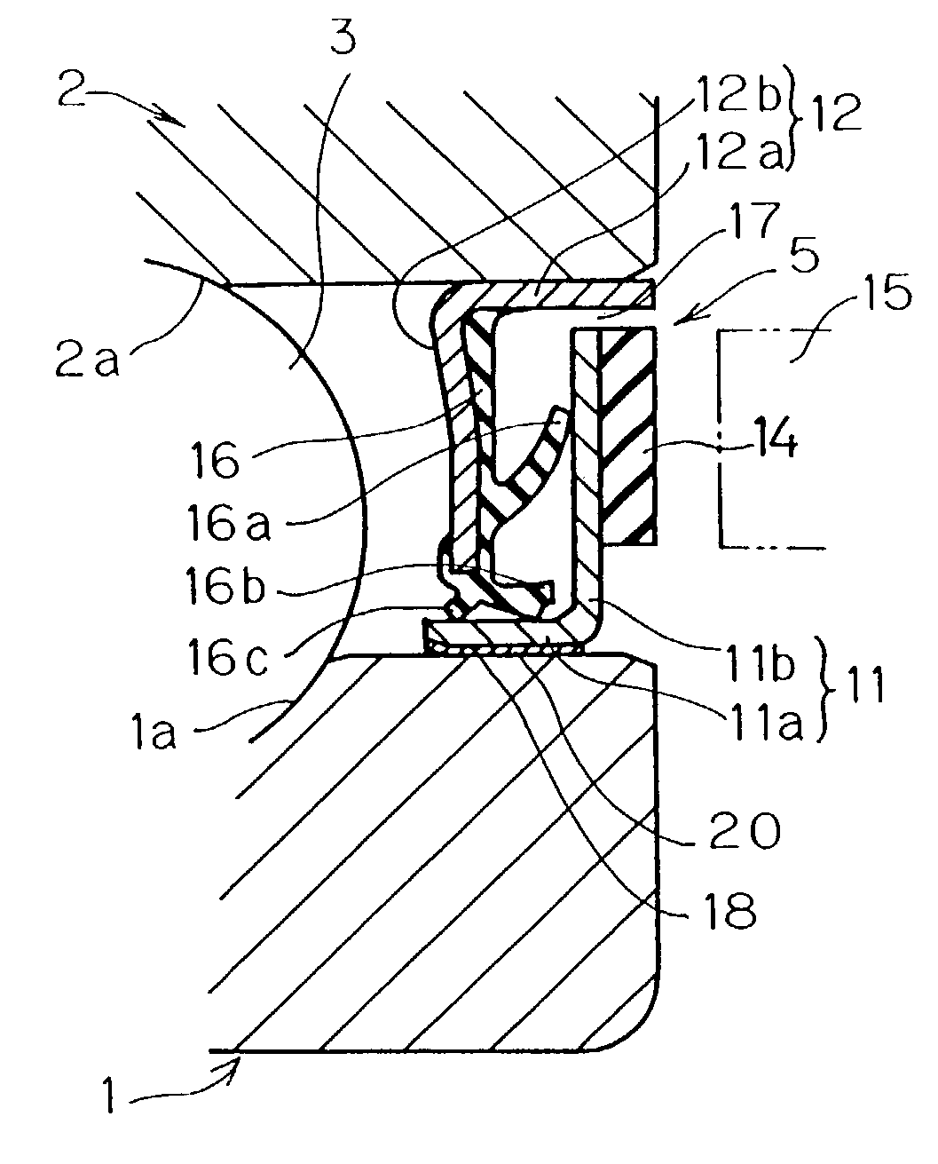
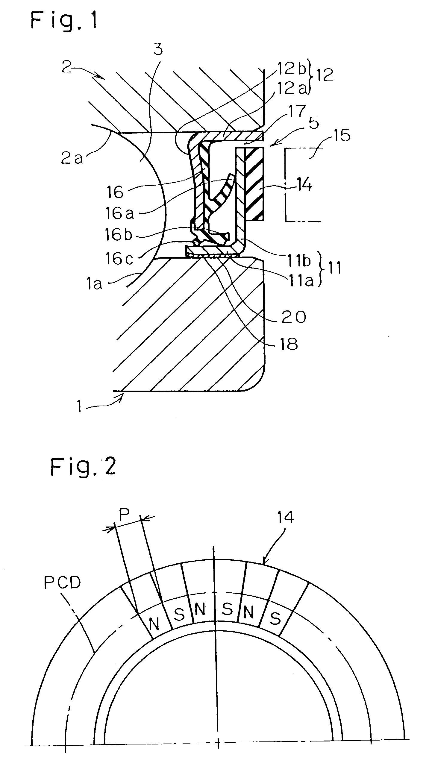
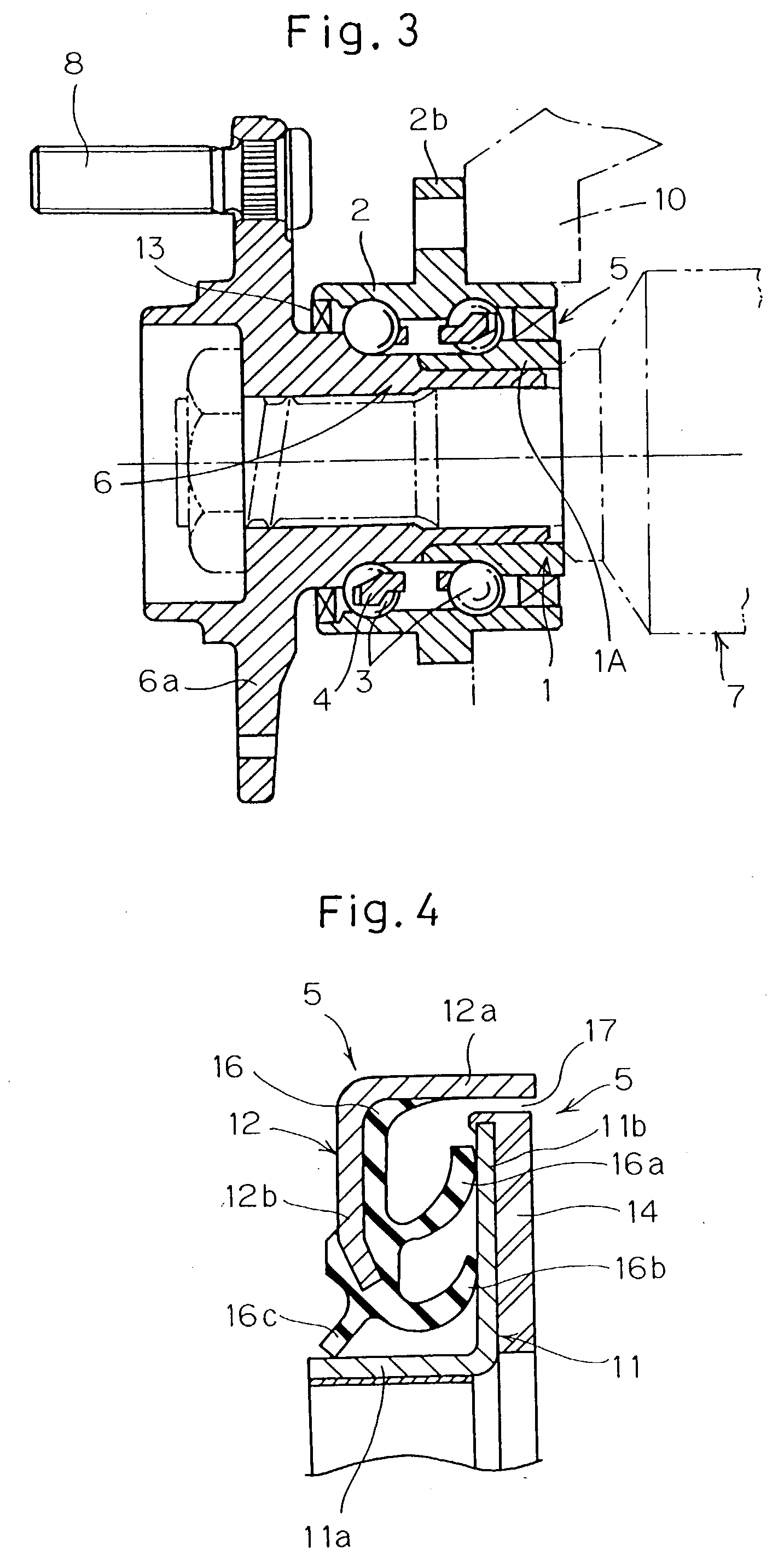
[0138] Preferred embodiments of the present invention will now be described. Referring first to FIG. 1, a wheel bearing shown therein includes an inner and outer members 1 and 2 rotatable relative to each other, a circular row of rolling elements 3 interposed rollingly between the first and second members 1 and 2, and a sealing device 5 for operatively sealing an annular end space delimited between the inner and outer members 1 and 2. Each of the inner and outer members 1 and 2 has a raceway 1a or 2a defined therein in the form of a generally semicircular sectioned groove. The inner and outer members 1 and 2 rollingly support the circular row of the rolling elements 3 and are positioned radially inwardly and outwardly of the circular row of the rolling element for rotation relative to each other. The inner and outer members 1 and 2 may respectively be inner and outer races of a rolling bearing or bearing inner and outer races combined together with separate component parts. Alternat...


PUM


Abstract

A wheel bearing includes a sealing device 5 positioned between inner and outer members 1 and 2. This sealing device 5 includes an elastic member 14, which eventually forms an encoder grid and is provided on a first annular sealing plate 11. A second annular sealing plate 12 is provided with sealing lips 16a to 16c. An engagement 18 between a cylindrical wall 11a of the first annular sealing plate 11 and the inner member 1 is provided with an elastic member 20 made of a material dissimilar to that for the elastic material 14. This elastic member 20 may be a rubber coated layer, resin paint layer, a thin film of adhesive material or a ring-shaped rubber member. Thereby, any possible ingress of water across an engagement surface of the annular sealing plate is prevented, accompanied by increase of the lifetime of the bearing, with no problem associated with separation and displacement of the annular sealing plates. The magnetic flux density can also be easily secured.

Description

[0001] 1. (Field of the Invention)[0002] The present invention generally relates to a sealing device in a wheel bearing for an automobile or the like and, more particularly, to the sealing device of a kind integrated together with an encoder grid.[0003] 2. (Description of the Prior Art)[0004] The wheel bearing including, as shown in FIG. 37, a sealing device 105 interposed between an inner member 101 and an outer member 102 rotatable to each other through a circular row of rolling elements 103 has been well known in the art. The sealing device 105 shown therein includes an encoder grid 106 integrated together therewith. In this connection, see the Japanese Laid-open Patent Publication No. 6-281018. The prior art sealing device 105 includes generally L-sectioned first and second annular sealing plates 107 and 108 fitted respectively to the inner and outer members 101 and 102 with an elastically deformable sealing lip member 109 secured to the second annular sealing plate 108 so as to...

Claims


Application Information

Patent Timeline
Patent Type & Authority Applications(United States)
IPC IPC(8): F16C19/18F16C19/52F16C33/78F16J15/32
CPCF16C19/186F16C33/64F16C41/007F16C2326/02F16C33/768F16J15/3264F16C33/7883F16C2240/40F16C33/783F16J15/326F16C2226/30F16C2226/40
Inventor OHTSUKI, HISASHINORIMATSU, TAKAYUKIFUNAHASHI, EIJIKAMETAKA, KOJINIKI, MOTOHARUSUGIYAMA, KATSUMIADACHI, KENRO
Owner NTN CORP
Why Eureka
Try Eureka