
Partial printing of a substrate with edge sealed printed portions

a printing portion and substrate technology, applied in the direction of printing process, duplicating/marking method, decorative arts, etc., can solve the problem of printing machine error or "tolerance", error or "tolerance" in the delivery of a substrate, and the inability to reliably produce with conventional printing methods withou

Inactive Publication Date: 2004-05-13
CONTRA VISION
View PDF11 Cites 27 Cited by
  • Summary
  • Abstract
  • Description
  • Claims
  • Application Information

AI Technical Summary

Benefits of technology

"The present invention relates to a method of printing a substrate with multiple layers that have inexact registration. The invention provides a way to produce panels with partially printed areas that have visually sealed edges, which can provide better control over color and other incident wave characteristics. The invention can be used for various applications such as visual and other functional effects, security printing, and production of panels with improved medication transfer control. The invention addresses the issue of inexact registration in conventional printing methods and provides a way to produce panels with substantially exact registration."

Problems solved by technology

However, these methods typically involve the use of special inks and additional production stages compared to the simple deposition of layers of ink or other marking material.
i) printing machine error or "tolerance" in delivering ink or other marking material,
iv) the error or "tolerance" in delivery of a substrate into the printing position.
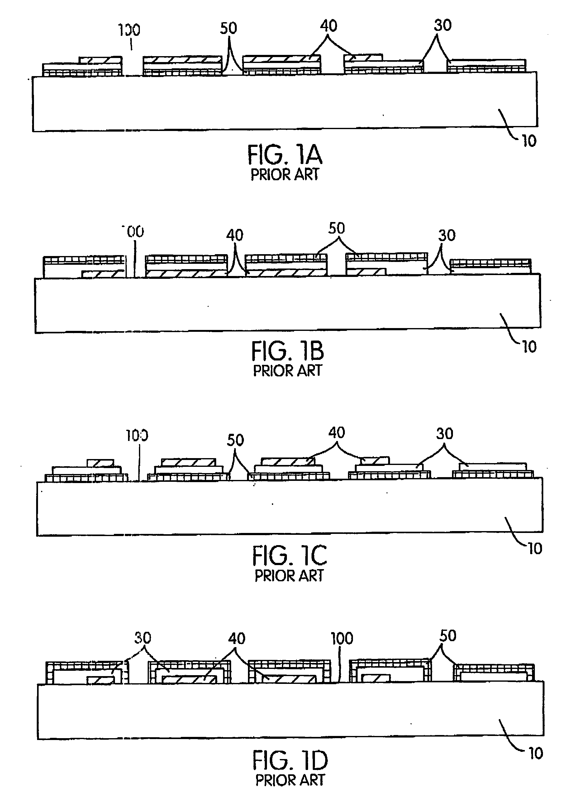
Panels according to US RE37,186 cannot be reliably produced with conventional printing methods without special measures to overcome the otherwise inevitable color variance from that desired, both over the area of a single panel and between panels within a production run.
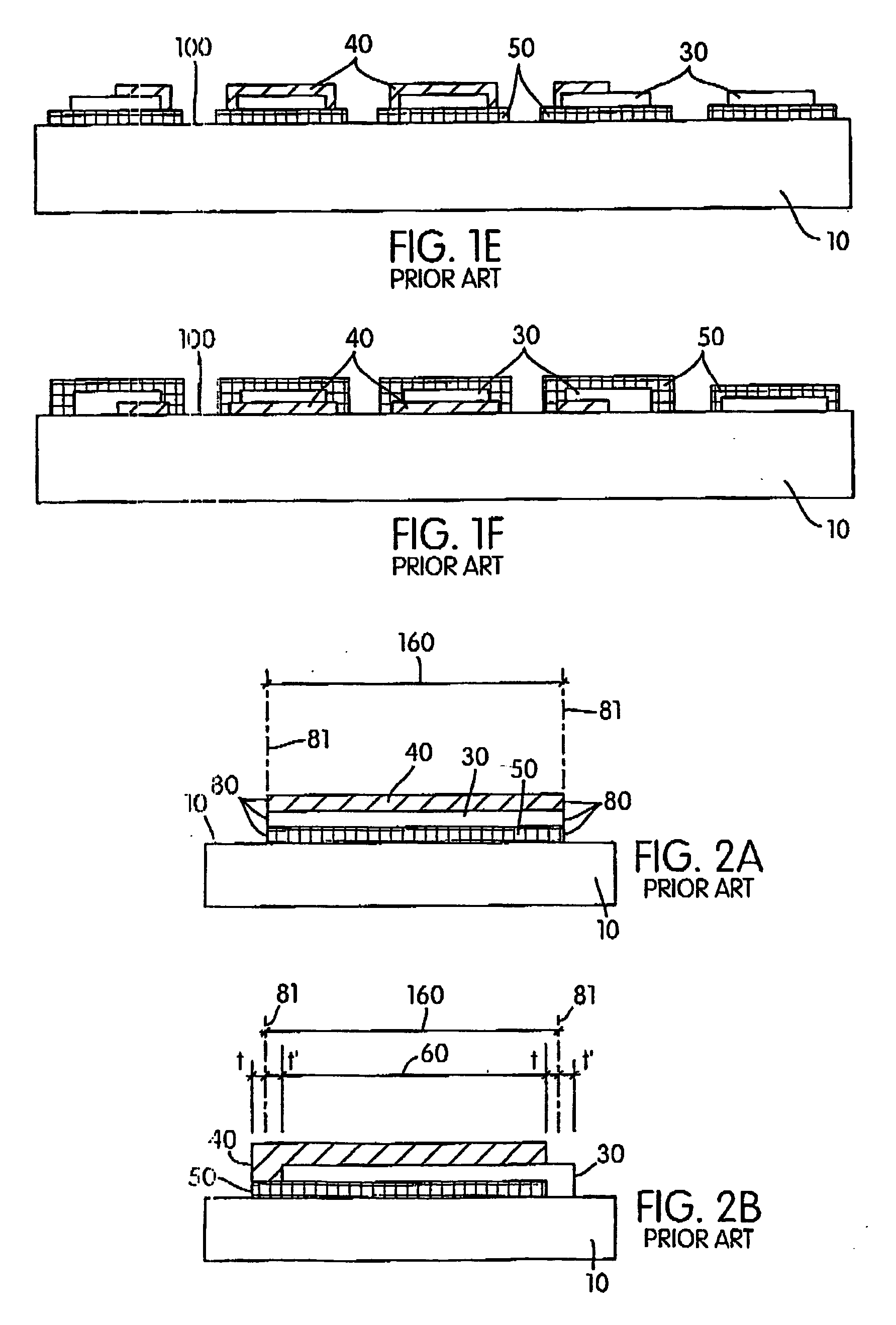
As outlined in U.S. Pat. No. 6,210,776, such registration errors will typically cause very substantial changes from the colors that are desired to be perceived on particular parts of a single panel, and variance from panel to panel in a production run.
Also, if design layer 40 comprises a translucent ink, for example a single "spot" translucent color ink or the cyan, magenta, yellow and black translucent inks of a CMYK four color process design, such lack of registration on a relatively small printed portion causes dramatic variance of perceived color from that desired.
This Lateral Combination Method has the disadvantage that there are always white edges visible throughout the panel and therefore design colors need to be adjusted to allow for this "whitening" of the printed design color ink.
Another disadvantage is that very dark design layer colors, including black, cannot be produced by a consistent application of this method, because of the presence of the white edges.
Another disadvantage of the "Through Combination Method" is that to achieve consistent color rendering, the design color inks are required to be translucent, in order for them to be rendered substantially invisible when overlapping directly onto the black layer.
While ink manufacturers typically provide `spot` colors in differing degrees of translucency, there is less choice and flexibility with a limitation to translucent inks.
Additionally, it is not possible to obtain ceramic inks that are sufficiently translucent for the Through Combination Method over the full range of desired colors.
The `Through Combination Method` is deficient in the manufacture of all such products incorporating design color layer inks which are not translucent or otherwise are clearly visible over a black layer.

Method used


Image

  • Partial printing of a substrate with edge sealed printed portions
  • Partial printing of a substrate with edge sealed printed portions
  • Partial printing of a substrate with edge sealed printed portions

Examples


Embodiment Construction

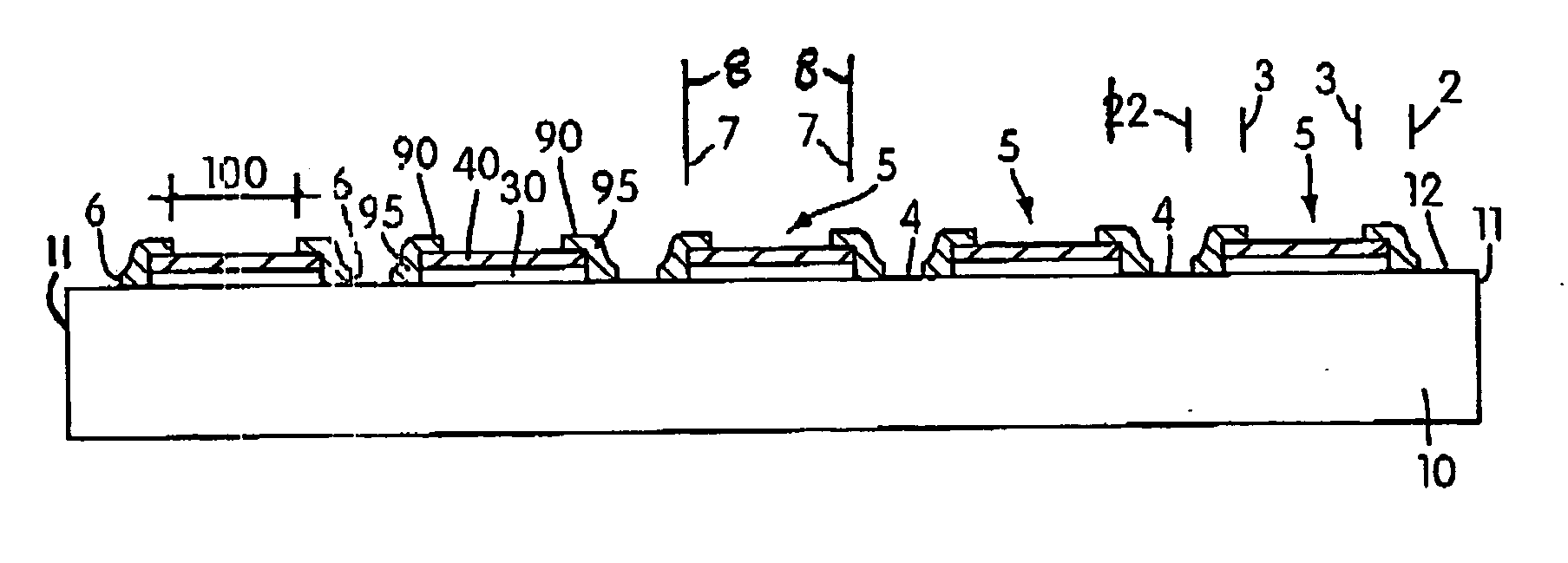
[0021] According to the present invention a panel comprises a substantially imperforate substrate and a print pattern disposed on said substrate, said print pattern being disposed on only part of said substrate and comprising at least three layers including a first layer, a second layer, and a control layer, said first layer, said second layer, and said control layer being configured and disposed such that a cross-section taken through said panel comprises two outer edges of said substrate and alternate printed portions of said substrate and unprinted portions of said substrate, each said printed portion having two outer edges, and wherein within said cross-section of said panel each of a plurality of said printed portions being constructed and arranged such that they each include a part of said first layer and a part of said second layer and a part of said control layer, said plurality of said printed portions each including two outer edges of said part of said first layer and two ...


PUM

PropertyMeasurementUnit
widthaaaaaaaaaa
widthaaaaaaaaaa
widthaaaaaaaaaa

Abstract

This invention relates to the partial printing of a substrate with a plurality of layers to form a partially printed panel. Within each printed portion, at least one layer is applied to the substrate with inexact registration in relation to a second layer. A "control layer" comprising "edge sealing strips" is printed so that, within each printed portion, each edge of the at least two layers with inexact registration is located within the edges of an overlapping edge sealing strip. The edge sealing strips may provide a visual seal or mask at the edges of printed portions, for example to enable the each printed portion to have the desired color rendering within a one-way vision control panel. The invention can comprise the physical sealing of printed portions containing gaseous or liquid fluids or particles in suspension, such as fragrances, medication, environmentally reactive materials or security printing features.

Description

[0001] The present invention claims priority from U.S. patent application Ser. No. 09 / 764,276 filed Jan. 19, 2001 and herein incorporated by reference.BACKGROUND TO THE INVENTION[0002] This invention relates to the partial printing of a substrate with a plurality of layers to form a partially printed panel. Within each printed portion, at least one layer is applied to the substrate with inexact registration in relation to a second layer. A "control layer" comprising "edge sealing strips" is printed so that, within each printed portion, each edge of the at least two layers with inexact registration is located within the edges of an overlapping edge sealing strip. The edge sealing strips may provide a visual seal or mask at the edges of printed portions, for example to enable the each printed portion to have the desired color rendering that would otherwise not be consistently achieved through lack of registration. There are many other applications for the invention, for example to con...

Claims


Application Information

Patent Timeline
Patent Type & Authority Applications(United States)
IPC IPC(8): B41M1/18B41M3/00B44C3/02B44C5/04B44F3/00
CPCB41M1/18B41M3/006B41M3/008B44C3/02Y10T428/2486B44F3/00Y10T428/24793Y10T428/24802Y10T428/24736B44C5/0446
Inventor HILL, ROLAND G.
Owner CONTRA VISION
Learn More