Connection device for electric accumulator

a technology of connecting device and electric accumulator, which is applied in the direction of coupling device connection, primary cell maintenance/servicing, batteries, etc., can solve the problems of reducing the electrical efficiency of the accumulator, introducing a risk of increasing the electrical resistance, and poor heat dissipation, so as to achieve low voltage drop and high contact quality

Inactive Publication Date: 2004-05-13
BLUE SOLUTIONS
View PDF6 Cites 20 Cited by
  • Summary
  • Abstract
  • Description
  • Claims
  • Application Information

AI Technical Summary

Benefits of technology

[0003] The purpose of the invention is to make a connection device for an accumulator in order to obtain high contact quality in the long term, a low voltage drop and protection against electrical overloads and abnormal temperature rises.

Problems solved by technology

The reliability of the connection interface may be influenced by corrosion or bad tightening, introducing a risk of increasing the electrical resistance.
The result is a large voltage drop that reduces the electrical efficiency of the accumulator, and poor dissipation of heat during operation of the accumulator.

Method used


Image

  • Connection device for electric accumulator
  • Connection device for electric accumulator
  • Connection device for electric accumulator

Examples


Embodiment Construction

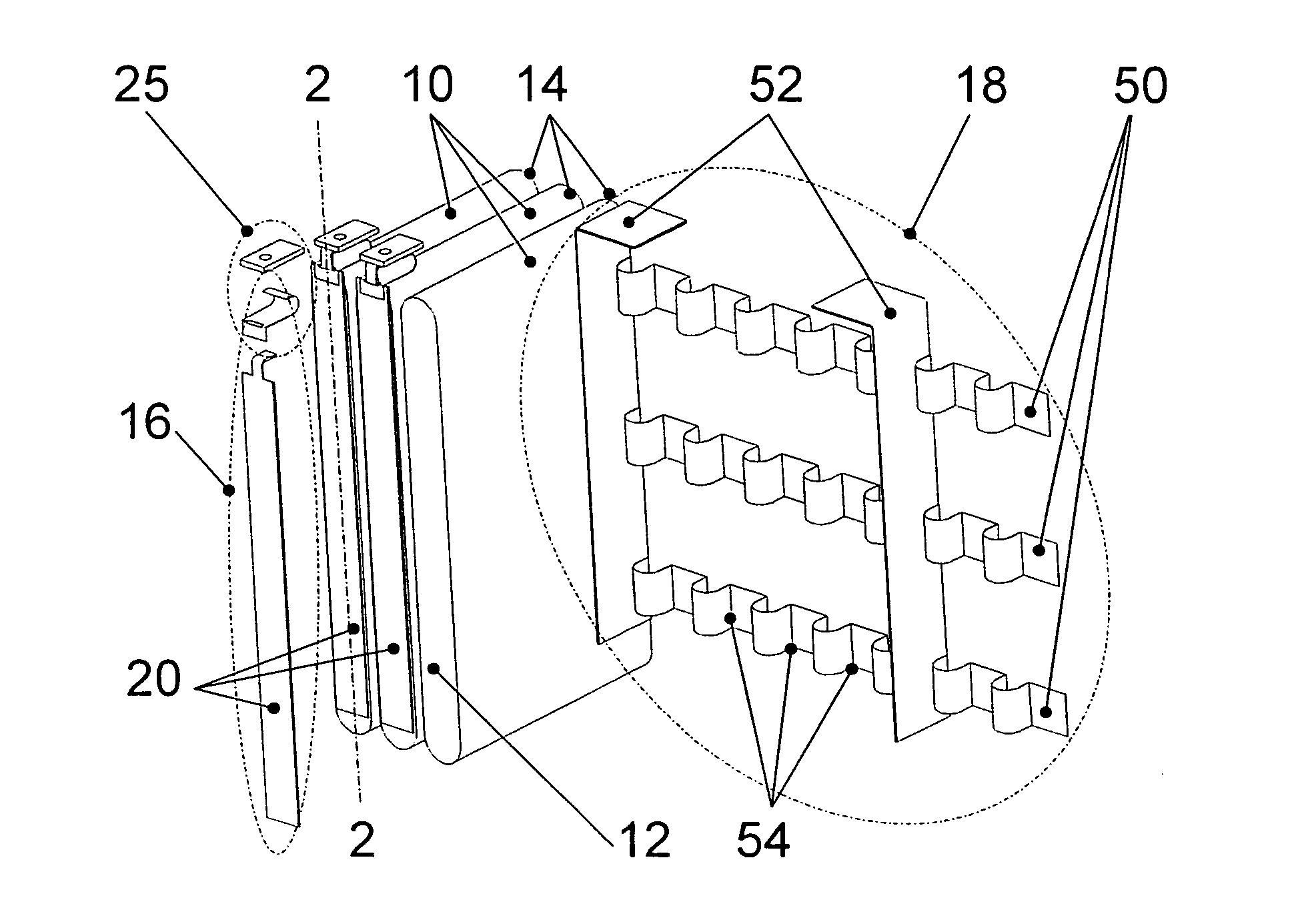
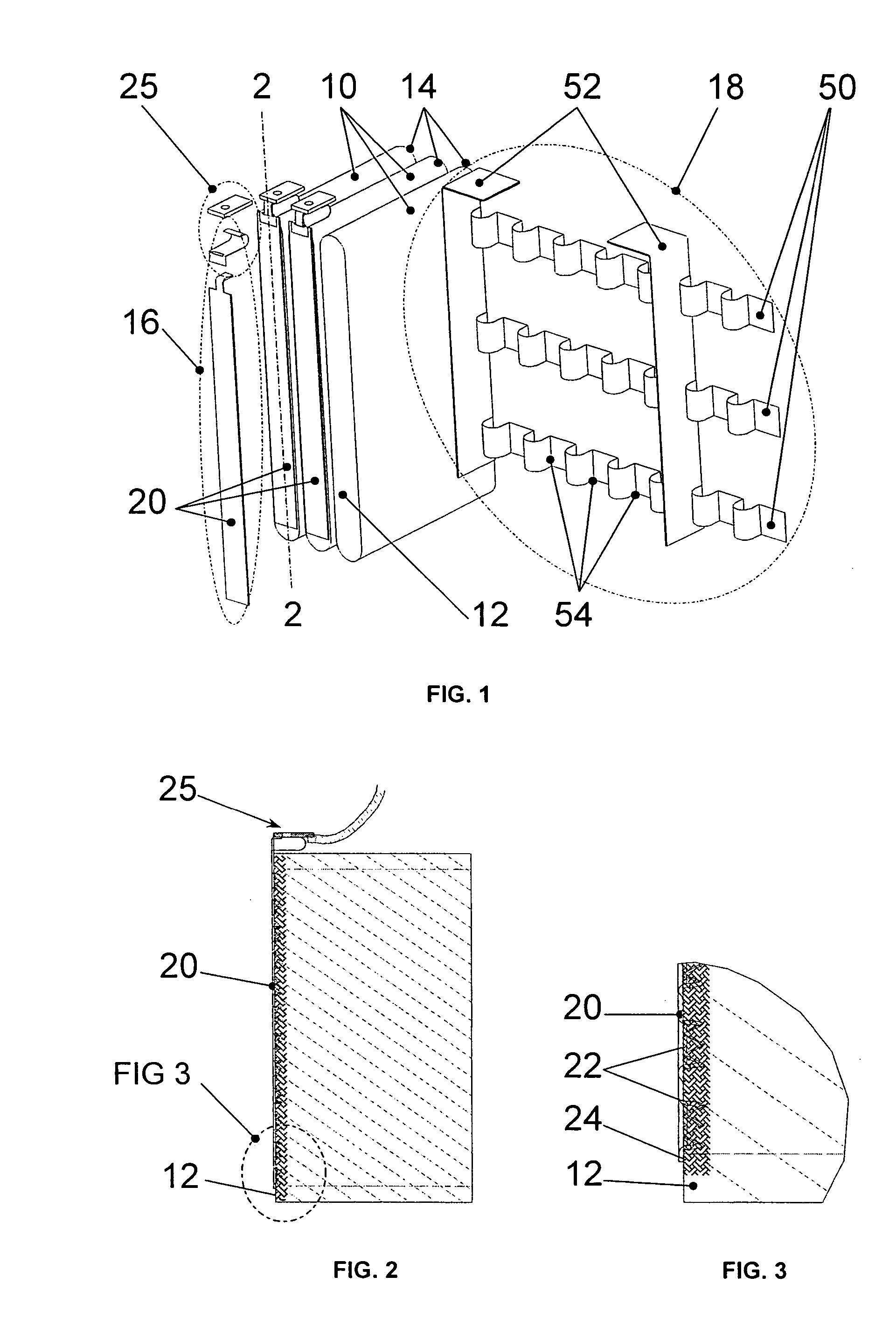
[0021] Modular accumulator elements 10 are installed side by side while remaining connected to an electrical connection device, as illustrated in FIGS. 1 to 3. The small opposite faces of each accumulator element 10 are provided with a pair of plane electrodes 12, 14, called the anode and the cathode respectively. The connection device is composed of a first connection subassembly 16 associated with the anode of each accumulator element 10, and a second connection subassembly 18 associated with the cathodes of the set of accumulator elements 10.

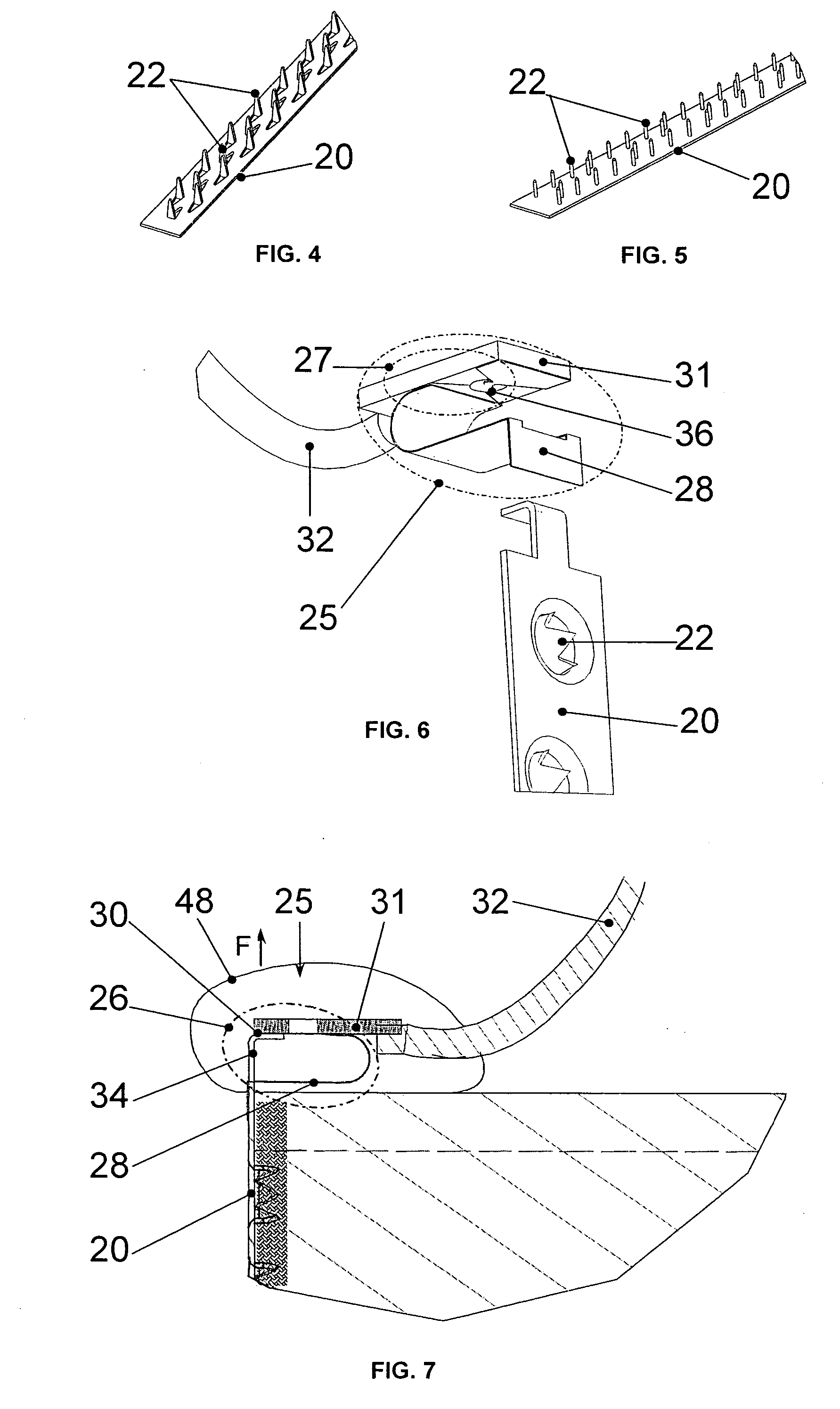
[0022] The first connection subassembly 16 of the anode is arranged to perform an electrical contact resistance function, and a temperature and / or electrical protection function. It comprises a rectangular metallic strip 20 made of a conducting material, with an internal surface on which several pins 22 are formed. The first electrode 12 is covered by a sheet 24 of soft metal, for example lithium, with which this strip 20 comes into contact. ...


PUM

PropertyMeasurementUnit
temperatureaaaaaaaaaa
pressureaaaaaaaaaa
conductingaaaaaaaaaa

Abstract

A connection device for an electric accumulator 10 a first connection subassembly 16 associated with one of the electrodes 12. It comprises a metallic conducting strip 20 provided with several pins that will be embedded in the electrode 12 to make the electrical contact, and temperature and / or electrical protection means housed in a fixed module 25 electrically connected to one of the ends of the strip 20.

Description

TECHNICAL DOMAIN OF THE INVENTION[0001] The invention relates to a connection device for an electric accumulator comprising a first connection subassembly associated with one of the electrodes, and a second connection subassembly associated with the other electrode.STATE OF THE ART[0002] Electrical connections for electric accumulators are usually made using connectors that are inserted into electrodes in the form of tabs, or screw-on collars fixed to conducting contacts with opposite polarities. The reliability of the connection interface may be influenced by corrosion or bad tightening, introducing a risk of increasing the electrical resistance. The result is a large voltage drop that reduces the electrical efficiency of the accumulator, and poor dissipation of heat during operation of the accumulator.PURPOSE OF THE INVENTION[0003] The purpose of the invention is to make a connection device for an accumulator in order to obtain high contact quality in the long term, a low voltage ...

Claims


Application Information

Patent Timeline
Patent Type & Authority Applications(United States)
IPC IPC(8): H01M6/50H01M50/528H01M50/533H01M50/534H01M50/536H01M50/541H01M50/583
CPCH01M2/26H01M2/34H01M2200/106H01M2200/103H01M2/348Y02E60/10H01M50/581H01M50/583H01M50/534H01M50/536H01M50/533
Inventor BARRAULT, MICHELBETTEGA, ERICCADOUX, YVAN
Owner BLUE SOLUTIONS
Why Eureka
Try Eureka