
High angle constant velocity joint

Inactive Publication Date: 2004-05-20
GKN AUTOMOTIVE INC
View PDF8 Cites 24 Cited by
  • Summary
  • Abstract
  • Description
  • Claims
  • Application Information

AI Technical Summary

Benefits of technology

[0013] Still a further object of the present invention is to provide a constant velocity joint that is balanced such that the shaft and tube will be capable of moving through the outer race in the event of a collision.
[0022] Still another advantage of the present invention is the use of a constant velocity joint that will allow assembly of the inner race into the cage without the use of cage grooves thus increasing the strength of the overall structure of the constant velocity joint.

Problems solved by technology

The plunging constant velocity joints allow for axial movement during the operation without the use of slip splines, but sometimes initiate forces that result in vibration and noises.
The sealing protection of the constant velocity joint is necessary because contamination of the inner chamber causes internal damage and destruction of the joint which increases heat and wear on the boot, thus inevitably leading to premature boot and grease failures and hence failure of the overall joint.
Thus, the increased temperatures because of higher angles along with increased stresses on the boot because of higher angles may result in premature failures of the prior art constant velocity joints.

Method used


Image

  • High angle constant velocity joint
  • High angle constant velocity joint
  • High angle constant velocity joint

Examples


Embodiment Construction

)

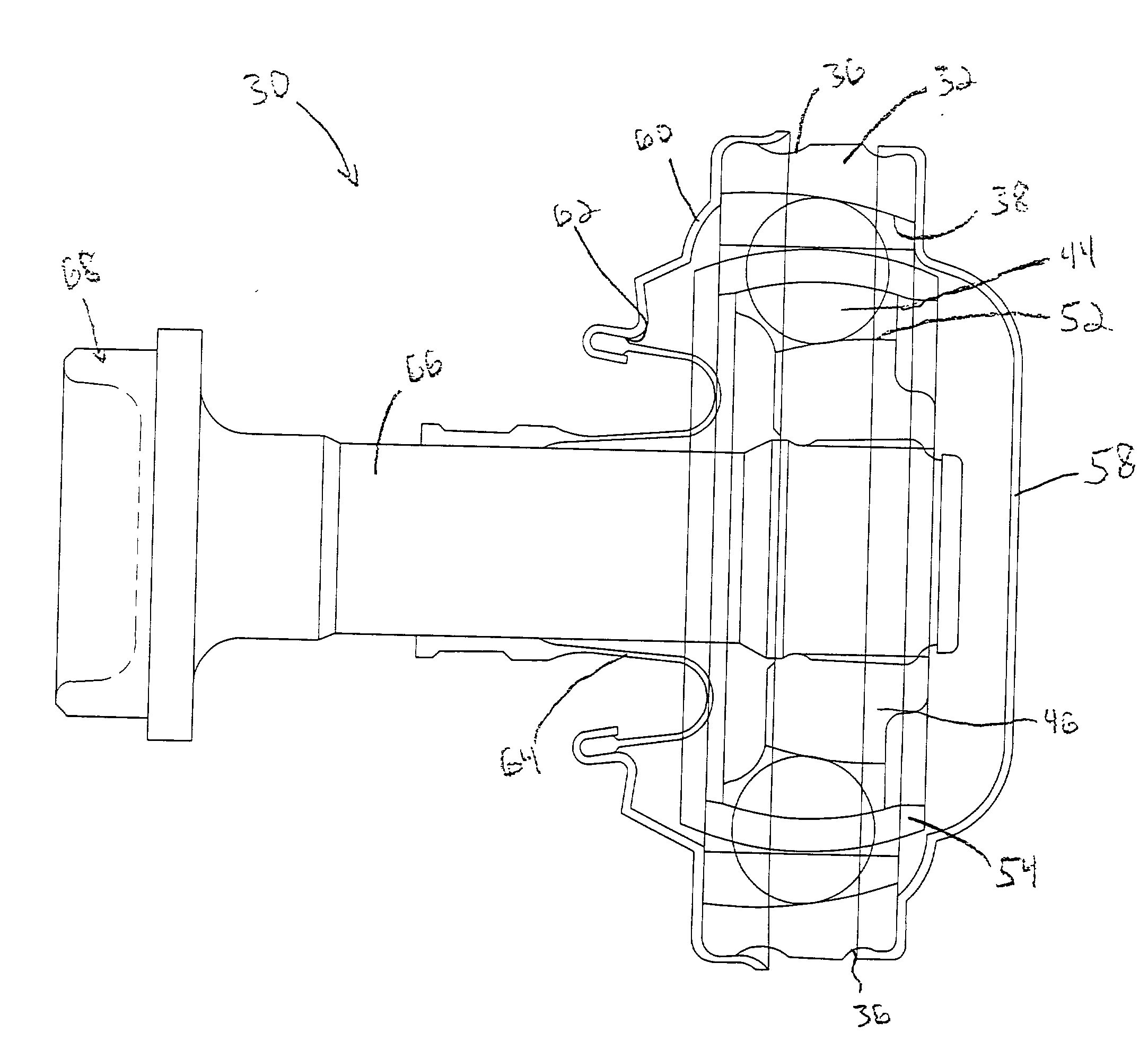
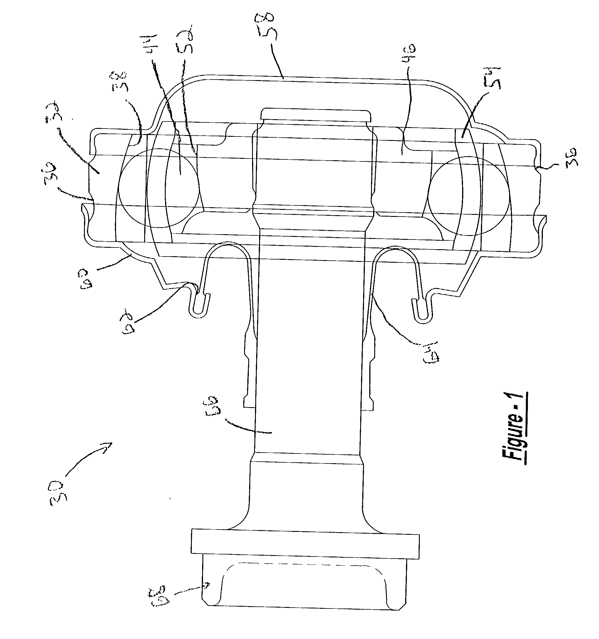
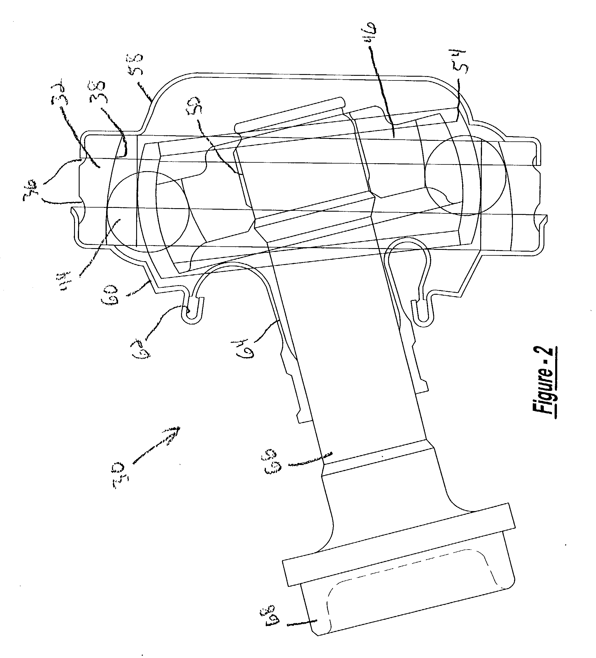
[0047] Referring to the drawings, a constant velocity joint 30 according to the present invention is shown. It should be noted that any type of constant velocity joint, such as a plunging tripod, a fixed tripod, etc may be used according to the present invention. The constant velocity joint 30 for the present invention generally is a high angle, high speed, ball type fixed constant velocity joint for use on a propeller shafts or drive shafts. The high angle can be defined as anything greater than or equal to nine degrees. These high angle joints tend to operate at high speeds and at higher temperatures.

[0048] A typical driveline for an all wheel drive vehicle includes a plurality of constant velocity joints 30. However, it should be noted that the present invention can also be used in rear wheel drive only vehicles, front wheel drive only vehicles, all wheel drive vehicles, and four wheel drive vehicles. Generally, a driveline includes an engine that is connected to a transmission ...


PUM


Abstract

A high angle constant velocity joint for use in a vehicle. The high angle constant velocity joint includes an outer race having a bore therethrough. The outer race also includes a plurality of tracks on an inside surface of the outer race. The constant velocity joint includes a cage arranged within the bore of the outer race without contacting the outer race. The constant velocity joint also includes an inner race arranged within the cage, the inner race having a plurality of tracks on an outer surface with one half of the tracks open in a direction opposite of another one half of the tracks on the inner race. The constant velocity joint also includes a plurality of large diameter balls arranged within the cage and tracks of the inner and outer race. The constant velocity joint has a shaft connected to the inner race and a pliable boot arranged between the outer race and the shaft. The constant velocity joint also includes a cap contacting the outer race. The high-speed, high angle constant velocity joint will allow for a more efficient and smaller package constant velocity joint for use in high angles and high speeds thus increasing the reliability of the boot and overall reliability of the constant velocity joint.

Description

[0001] 1. Field of the Invention[0002] The present invention generally relates to constant velocity joints and more particularly, relates to a high angle, high-speed constant velocity joint.[0003] 2. Description of the Related Art[0004] Constant velocity joints (CV joints) are common components in automotive vehicles. Typically, constant velocity joints are employed where transmission of a constant velocity rotary motion is desired or required. Common types of constant velocity joints are a plunging tripod, a fixed tripod, a plunging ball joint, and a fixed ball joint. These joints can be used in front wheel drive vehicles, or rear wheel drive vehicles and on the propeller shafts found in rear wheel drive, all wheel drive and four wheel drive vehicles. The plunging constant velocity joints allow for axial movement during the operation without the use of slip splines, but sometimes initiate forces that result in vibration and noises. The plunging types allow angular displacement alon...

Claims


Application Information

Patent Timeline
IPC IPC(8): F16D3/223
CPCF16D3/223Y10S464/906F16D2003/22309F16D2003/22303
Inventor DINE, DONALD W.
Owner GKN AUTOMOTIVE INC
Features
  • Generate Ideas
  • Intellectual Property
  • Life Sciences
  • Materials
  • Tech Scout
  • Unparalleled Data Quality
  • Higher Quality Content
  • 60% Fewer Hallucinations
Learn More