Vehicular suspension

a technology for suspensions and vehicles, applied in the direction of suspension arms, resilient suspensions, vehicle components, etc., can solve the problems of reducing strength and durability, reducing the load when braking, and difficulty in obtaining a sufficient weld strength

Inactive Publication Date: 2004-05-27
F TECH INC
View PDF5 Cites 10 Cited by
  • Summary
  • Abstract
  • Description
  • Claims
  • Application Information

AI Technical Summary

Benefits of technology

[0012] With this arrangement, the flat first seating surface provided at the rear end of the trailing arm and the flat second seating surface provided at the outer end of the flexible arm are superimposed on each other, and the inner periphery of the closed opening formed on the second seating surface or the inner periphery of the channel with one end open formed on the second seating surface is welded to the first seating surface. Therefore, when a longitudinal load acts on the wheel W and the outer end of the flexible arm flexes longitudinally, the stress acting on the weld can be reduced, thereby enhancing the strength and the durability of the weld. In particular, since the first and second seating surfaces are in surface contact with each other, and the weld is formed along the inner periphery of the opening or the channel formed on the second seating surface of the flexible arm, it is possible to eliminate the starting point of a weld bead, which is a drawback in terms of the strength, thus further enhancing the reliability of the weld, and it is also possible to minimize the length of the weld bead, thereby contributing to reduction of the operation time and the cost.
[0013] Further, since both the first and second seating surfaces are flat, not only is the mutual positioning of the two seating surfaces during welding easy, but also the welding can be carried out while the first seating surface is fixed so as to face upward, thus eliminating the need for changing the attitude of the trailing arm and the flexible arm to improve the workability of the welding. Furthermore, since the two flat seating surfaces can slide over each other, the relative positions thereof can be changed easily.
[0014] Moreover, since there is no need to make an outer end part of the flexible arm in a bifurcated shape and to sandwich a rear end part of the trailing arm from above and below, the height of the outer end part of the flexible arm can be made to substantially coincide with the height of the rear end part of the trailing arm, thus reducing the vertical dimension of the outer end part of the flexible arm to increase the degrees of freedom in the design.
[0016] In accordance with this arrangement, since the second seating surface projects relative to the main body portion of the flexible arm, the rigidity of the flexible arm can be increased in the vicinity of the second seating surface, thereby further improving the strength and the durability of the weld.

Problems solved by technology

In this type of suspension 01, a large load acts on the welds w1 and w2 between the rear end of the trailing arm 02 and the outer end of the lower arm 03, causing a problem that the strength and the durability decrease.
In particular, the load when braking is larger than that when accelerating.
Since the lower arm 03 is formed from a plate-like material, the lower arm 03 and the trailing arm 02 are in substantially line contact with each other, so that it is difficult to obtain a sufficient weld strength.
Further, since the beads of the welds w1 and w2 have end parts, stress might be concentrated in the end parts, causing a problem that they easily become the starting point for a fracture.
Moreover, since the bifurcated first and second support portions 03a and 03b are formed at the outer end of the lower arm 03, the vertical dimension of the lower arm 03 increases, causing a problem that the degrees of freedom are decreased in designing the suspension 01.

Method used


Image

  • Vehicular suspension
  • Vehicular suspension
  • Vehicular suspension

Examples


Embodiment Construction

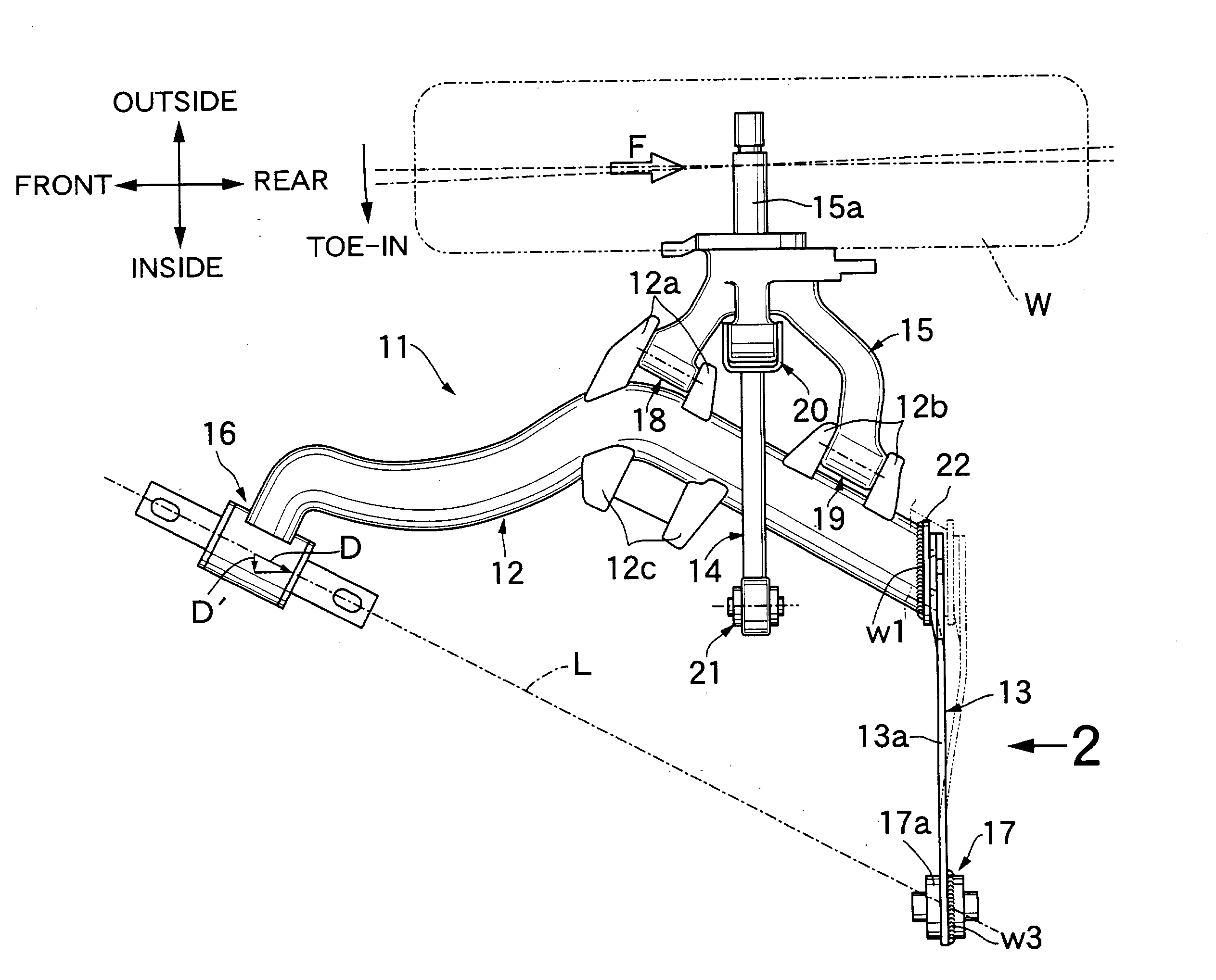
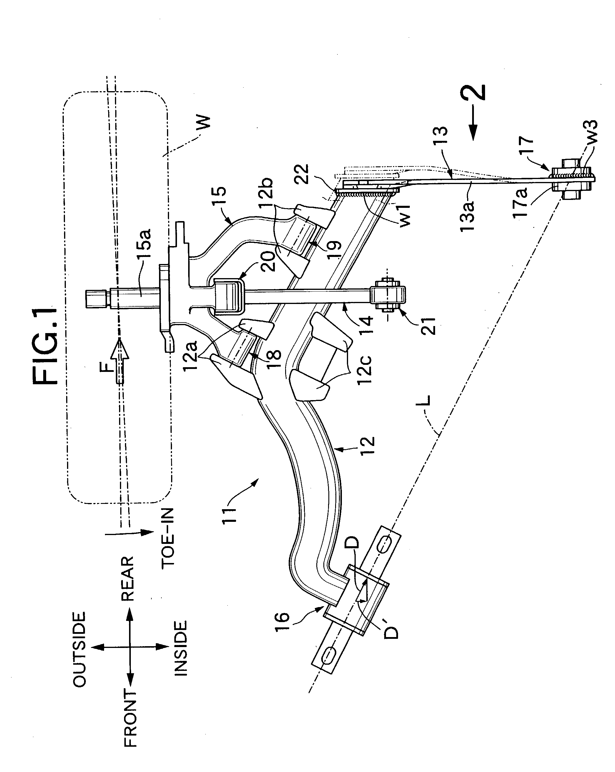
[0028] Referring to FIG. 1, a suspension 11 suspends a wheel W (right rear wheel) and includes a trailing arm 12, a lower arm 13, an upper arm 14, and a knuckle 15. The wheel W is rotatably supported on an axle 15a extending from the knuckle 15 outward in the vehicle width direction.

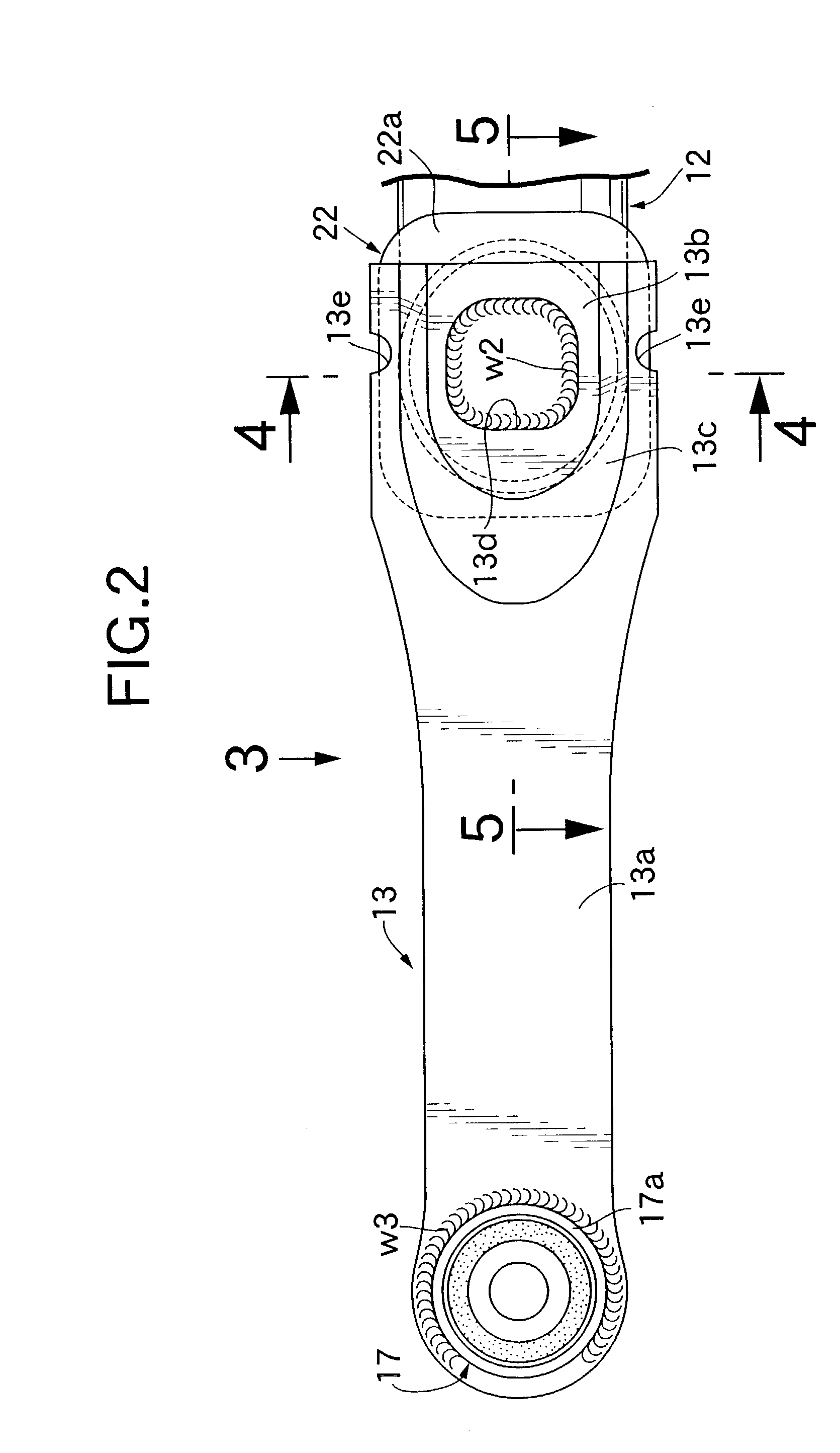
[0029] The trailing arm 12 is formed by bending a pipe material having a circular cross-section, the front end thereof is pivotably supported on a vehicle body via a joint 16, the rear end thereof is welded to the outer end of the lower arm 13, and the inner end of the lower arm 13 is pivotably supported on the vehicle body via a joint 17. Provided at positions to the rear of the middle of the trailing arm 12 are front brackets 12a and rear brackets 12b pivotably supporting lower parts of the knuckle 15 via joints 18, 19. Pivotably supported via a joint 20 on an upper part of the knuckle 15 is the outer end of the upper arm 14 with its inner end being pivotably supported on the vehicle body via a joint 2...


PUM


Abstract

A vehicular suspension includes a trailing arm and a substantially plate-like lower arm. The trailing arm is pivotably supported at its front end on a vehicle body via an elastic joint and extends from the front end toward the rear of the vehicle body. The lower arm extends in the vehicle width direction with its inner end pivotably supported on the vehicle body and its outer end fixed to a rear part of the trailing arm. A flat first seating surface of an end plate welded to the rear end of the trailing arm is superimposed on a flat second seating surface provided at the outer end of the lower arm, and an inner periphery of a closed rectangular opening formed on the second seating surface is welded to the first seating surface by a weld. The second seating surface of the lower arm protrudes from a main body portion via a slant surface.

Description

[0001] 1. Field of the Invention[0002] The present invention relates to a vehicular suspension that includes a trailing arm extending in the longitudinal direction of a vehicle body and a flexible arm extending in the vehicle width direction, wherein the outer end of the flexible arm is connected to the rear end of the trailing arm and flexes rearward when a wheel is braked, thereby making the wheel toe-in.[0003] 2. Description of the Related Art[0004] FIG. 7 and FIG. 8 show a conventional vehicular suspension. A suspension 01 suspends a wheel W (right rear wheel) and includes a trailing arm 02, a lower arm 03, an upper arm 04, and a knuckle 05. The front end of the trailing arm 02 is pivotably supported on a vehicle body via a joint 06. The inner end of the lower arm 03 is pivotably supported on the vehicle body via a joint 07. The outer end of the lower arm 03 is welded to the rear end of the trailing arm 02. The outer end and the inner end of the upper arm 04 are pivotably suppor...

Claims


Application Information

Patent Timeline
Patent Type & Authority Applications(United States)
IPC IPC(8): B60G3/10B60G3/28B60G3/20B60G7/00
CPCB60G3/20B60G2206/8201B60G2206/121B60G7/001
Inventor INOUE, MITSURUMIDORIKAWA, JUNICHI
Owner F TECH INC
Why Eureka
Try Eureka