
Method of correcting a screen printer and a board inspection system using the same

a screen printer and inspection system technology, applied in the direction of printing, circuit inspection/indentification, printed circuit aspects, etc., can solve the problems of reducing the reliability of the mounting process of electronic components, and achieve the effect of increasing the reliability of the solder forming process, facilitating the analysis of which process to apply, and increasing the reliability of the stencil mask position

Active Publication Date: 2015-07-30
KOHYOUNG TECH +1
View PDF7 Cites 9 Cited by
  • Summary
  • Abstract
  • Description
  • Claims
  • Application Information

AI Technical Summary

Benefits of technology

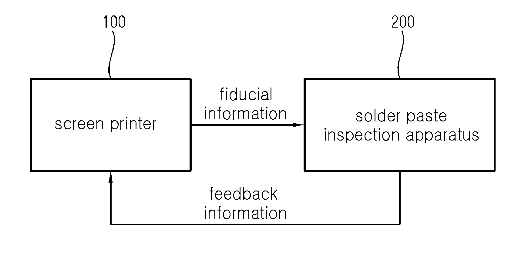
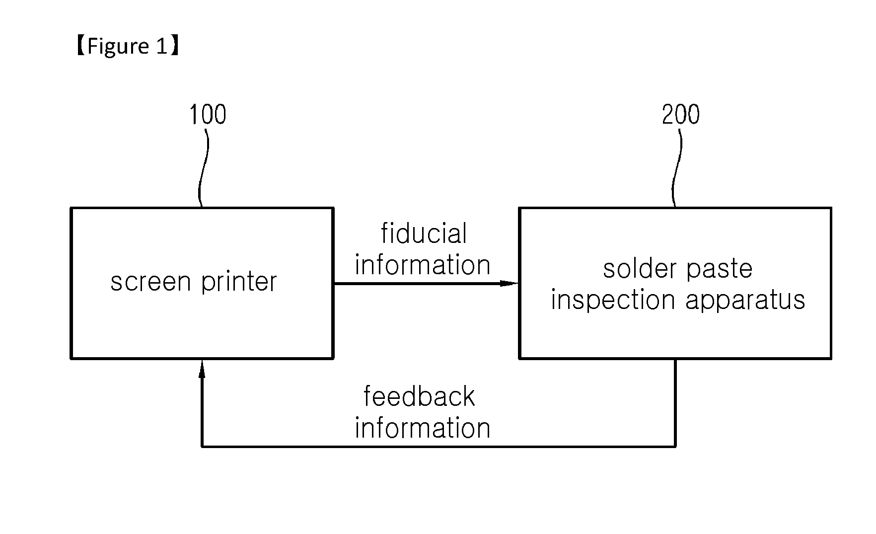
This patent describes a method to increase the reliability of a screen printer by using a feedback of an x,y offset value and rotating amount of a stencil mask from a solder paste inspection apparatus. The method also suggests dividing the board into multiple blocks to estimate the full x,y offset value and rotating amount of the stencil mask. Additionally, the method includes a statistical analysis of the printing condition change and the changed printed board to help optimize the process. Overall, the method improves the process of correcting the screen printer and increases its reliability.

Problems solved by technology

However, during process of printing a solder through a screen printer, a position error of a printed solder is actually generated by a misalignment of stencil mask, a mismatch between coordinate of fiducial mark camera which is inside screen printer and corrected coordinate of mask or board, etc, and therefore, a reliability of mounting process of electronic component is reduced.

Method used


Image

  • Method of correcting a screen printer and a board inspection system using the same
  • Method of correcting a screen printer and a board inspection system using the same
  • Method of correcting a screen printer and a board inspection system using the same

Examples


Embodiment Construction

[0034]The present invention is described more fully hereinafter with reference to the accompanying drawings, in which example embodiments of the present invention are shown. The present invention may, however, be embodied in many different forms and should not be construed as limited to the example embodiments set forth herein. Rather, these example embodiments are provided so that this disclosure will be thorough and complete, and will fully convey the scope of the present invention to those skilled in the art. In the drawings, the sizes and relative sizes of layers and regions may be exaggerated for clarity.

[0035]It will be understood that, although the terms first, second, third etc. may be used herein to describe various elements, components, regions, layers and / or sections, these elements, components, and / or sections should not be limited by these terms. These terms are only used to distinguish one element, component, region, layer or section from another region, layer or secti...


PUM


Abstract

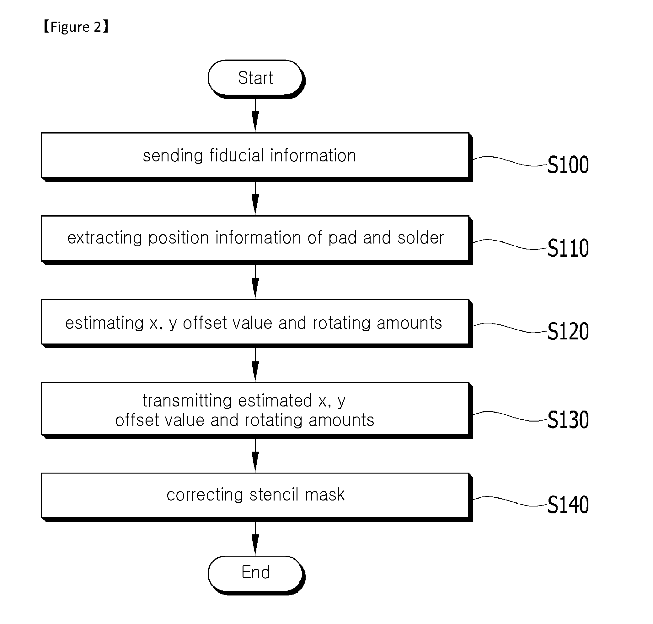
The present invention relates to a method of correcting a position of a stencil mask which comprises receiving fiducial information from a screen printer, extracting position information of a pad and position information of a solder formed on a board through measuring by a solder paste inspection apparatus, estimating an x, y offset value and a rotating amount of a stencil mask based on the fiducial information by using the position information of the pad and the solder, and transmitting the x,y offset value and the rotating amount of the stencil mask to the screen printer. Thus, a reliability of solder forming process may be increased by correcting a stencil mask position by transmitting a feedback of an x,y offset value and a rotating amount of the stencil mask from a solder paste inspection apparatus, in which the x,y offset value and the rotating amount are estimated based on fiducial information transmitted from the screen printer.

Description

TECHNICAL FIELD[0001]Exemplary embodiments of the present invention relate to a method of correcting a screen printer and a board inspection system using the same. More particularly, exemplary embodiments of the present invention relate to a screen printer which forms a solder on a board, a method of correcting a screen printer by using communication between a solder paste inspection apparatus which inspects a solder formed on a board, and a board inspection system using the same.BACKGROUND ART[0002]In general, in order to mount an electronic component on a printed circuit board, first, a solder is formed on a pad of a printed circuit board through a screen printer. Next, a solder forming state is inspected by a solder paste inspection (SPI) apparatus, and then, an electronic component is mounted through surface mount technology (SMT).[0003]Herein, a solder is formed on a pad of a printed circuit board by forming a solder on a stencil mask, which is disposed above a printed circuit ...

Claims


Application Information

Patent Timeline
Patent Type & Authority Applications(United States)
IPC IPC(8): B41F33/00B41F15/08
CPCB41F15/08B41F33/00H05K3/34H05K3/0008H05K3/1216H05K2201/09918H05K1/0269B41F15/0881B41F15/12B41F33/0036B41M1/12H05K3/3485B41F33/0081B41F15/14
Inventor KIM, MIN-YOUNGKIM, MIN-SUKIM, JA-GEUN
Owner KOHYOUNG TECH
Learn More