Welding device used for pipeline and using method of welding device

A technology for welding devices and pipes, which is applied to other manufacturing equipment/tools, manufacturing tools, etc., and can solve problems such as inconvenient portability and large limitations

Inactive Publication Date: 2021-05-28
刘少波
View PDF8 Cites 7 Cited by
  • Summary
  • Abstract
  • Description
  • Claims
  • Application Information

AI Technical Summary

Problems solved by technology

The pipeline welding device in the above-mentioned patent has the following disadvantages: although certain

Method used


Image

  • Welding device used for pipeline and using method of welding device
  • Welding device used for pipeline and using method of welding device
  • Welding device used for pipeline and using method of welding device

Examples


Embodiment 1

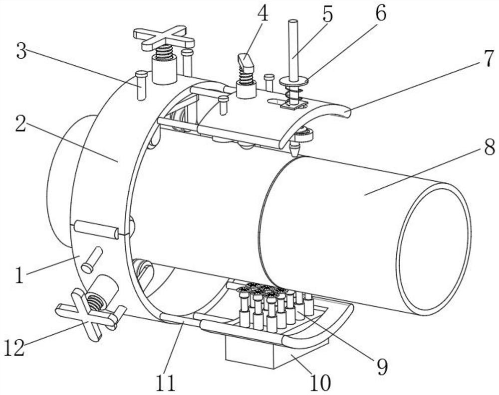
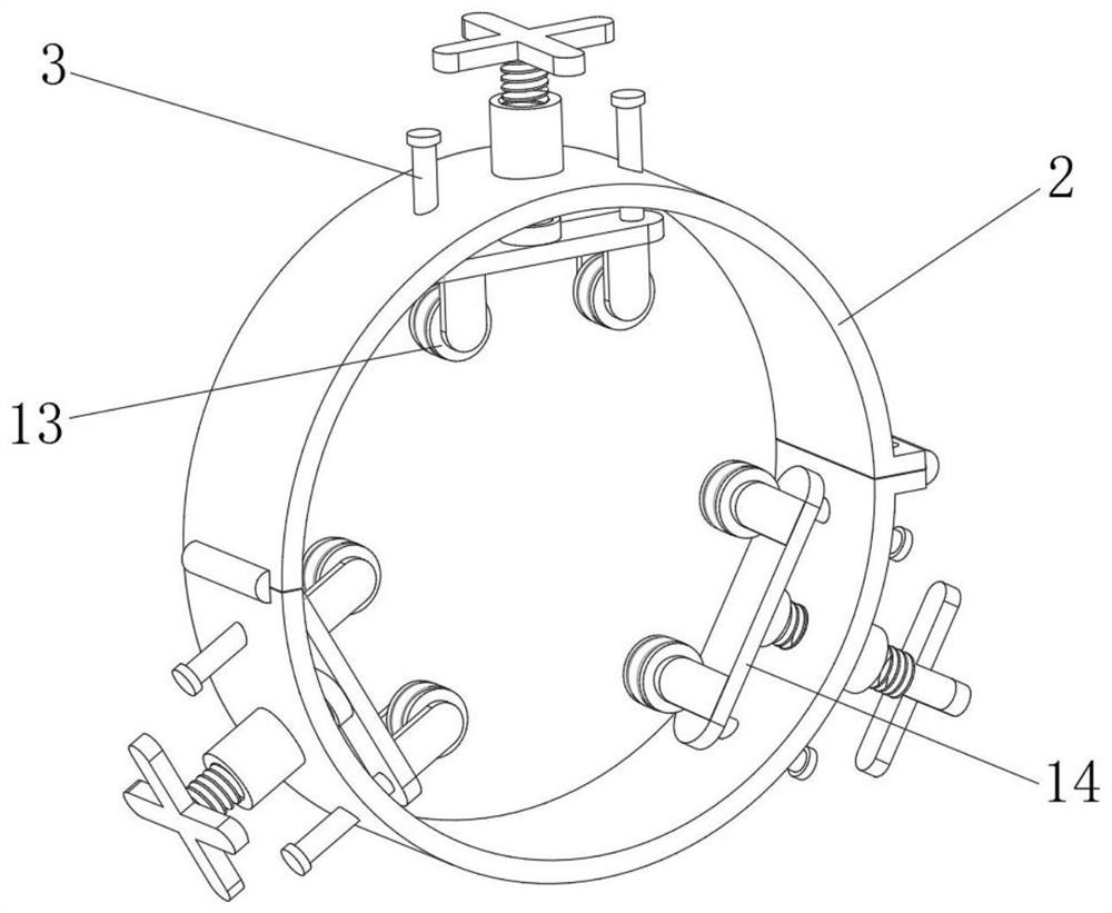
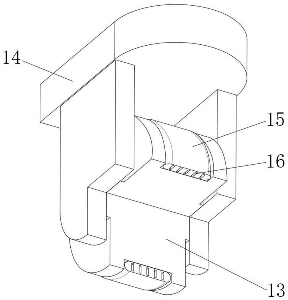
[0039] A welding device for pipes such as Figure 1-5As shown, it includes a lower fixing base 1 and an upper fixing base 2 installed on the pipeline 8, the lower fixing base 1 is fixed on the outer walls of the upper fixing base 2 through hinges and buckles, the lower fixing base 1 and the upper fixing base The seat 2 is a matching semi-circular structure; the inner wall of the lower fixed seat 1 and the upper fixed seat 2 is threadedly connected with more than three fixed knobs 12 equidistantly distributed, and one end of the fixed knob 12 is rotatably connected with a mounting Frame 14, described mounting frame 14 near the side outer wall of pipeline 8 is equipped with roller 13 by axle, and roller 13 peripheral walls are tangent to the peripheral wall of pipeline 8; Two first guide columns 3, the first guide column 3 is slidingly connected to the inner wall of the lower fixing base 1 or the upper fixing base 2; Seat 7 and lower mounting base 31, described upper mounting b...

Embodiment 2

[0048] A method for using a welding device for pipelines, comprising the steps of:

[0049] S1: Install the lower fixing seat 1 and the upper fixing seat 2 on the pipe 8 through buckles;

[0050] S2: adjust the position of the mounting bracket 14 through the fixing knob 12, so that the rollers 13 are attached to the outer wall of the pipe 8;

[0051] S3: Install the grinding seat 10 on the lower mounting seat 31, and adjust the position of the lower mounting seat 31, so that the grinding head 29 fits with the outer wall of the pipeline 8;

[0052] S4: Rotate the lower fixing seat 1 and the upper fixing seat 2, and use the grinding head 29 to grind the welded part of the pipe 8;

[0053] S5: After finishing the grinding, remove the grinding mechanism, and control the welding torch assembly 5 to work;

[0054] S6: Continue to rotate the lower fixing seat 1 and the upper fixing seat 2, and control the welding torch assembly 5 to move back and forth in the waist-shaped mouth 21,...


PUM


Abstract

The invention discloses a welding device used for a pipeline and a using method of the welding device, and relates to the technical field of pipeline welding. The portability and the grinding quality are both considered. The welding device comprises a lower fixing seat and an upper fixing seat which are installed on the pipeline, the lower fixing seat is fixed to the outer walls of the two ends of the upper fixing seat through hinges and clamping buckles, and the lower fixing seat and the upper fixing seat are both of matched semicircular structures; and the using method of the welding device comprises the following steps that the lower fixing seat and the upper fixing seat are installed on the pipeline through the clamping buckles, and the position of a mounting frame is adjusted through fixing rotary knobs, so that all rolling wheels are attached to the outer wall of the pipeline. According to the pipeline and the using method of the welding device, the fixing rotary knobs, the rolling wheels, a welding mechanism and other structures are arranged, the lower fixing seat and the upper fixing eat can be installed on a to-be-welded pipeline, reliable welding is carried out on the pipeline in a mode of rotating on the outer wall of the pipeline, and therefore the welding flatness is guaranteed, meanwhile, the welding device can adapt to pipelines of different sizes, and the universality and the welding quality are improved.

Description

technical field [0001] The invention relates to the technical field of pipeline welding, in particular to a welding device for pipelines and an application method thereof. Background technique [0002] In the process of pipeline construction, in order to meet the size and layout requirements of the site, it is often necessary to assemble and connect different pipelines. The assembly and connection usually adopts welding. The current welding channel is only carried out by hand-held welding guns, etc. Although this method can meet Welding needs, however, the welding place tends to be relatively uneven, which is not only unsightly, but also the welding quality cannot be guaranteed; some equipment is used for welding, but there are problems of inconvenient portability and large limitations. [0003] After retrieval, the Chinese patent application number is CN201921070319.6, which discloses a pipeline welding device for building fire protection, including a base, the right side o...

Claims


Application Information

Patent Timeline
IPC IPC(8): B23P23/00
CPCB23P23/00
Inventor 刘少波
Owner 刘少波
Why Eureka
Try Eureka