Hermetically sealed battery

Inactive Publication Date: 2009-05-28
HITACHI MAXELL ENERGY LTD
4 Cites 15 Cited by

AI-Extracted Technical Summary

Problems solved by technology

However, aluminum or an aluminum alloy cannot be considered to have good welding compatibility with nickel, a nickel alloy, or the like, and when the entire seal is formed of aluminum or the like, the weld strength of the lead is disadvantageously decreased.
Consequently, the nickel layer is melted and evaporated, resultin...

Method used

[0019]Since a lead 30 can be welded onto the dissimilar metal layer 26 formed of nickel, stainless steel, or the like, good weld strength of the lead 30 can also be ensured. The seal, which is given the function of the terminal plate, reduces the number of components and can also contribute to a reduction in the manufacturing cost of the hermetically sealed battery.
[0020]In addition, since the seal 17 is welded by the laser beam 27 so that an edge 29a of a welding mark 29 is positioned outside the outer peripheral edge 26a of the dissimilar metal layer 26, the occurrence of so-called spatters, that is, melting and spattering of the dissimilar metal layer 26 can be prevented, and thus the occurrence of welding defects can also be reliably prevented.
[0021]Specifically, since the aluminum layer 25 has greater thermal conductivity than the dissimilar metal layer 26, the aluminum layer 25 easily diffuses heat generated by the laser beam 27. For this reason, the irradiation energy of the laser beam 27 is set to a higher level than in the case where, for example, nickel is welded. Thus, when the heat generated by the laser beam 27 at such a high energy is transmitted to the dissimilar metal layer 26, the temperature of the dissimilar metal layer 26 is elevated accordingly because the dissimilar metal layer 26 does not easily diffuse heat. Consequently, the dissimilar metal layer 26 is melted and evaporated, resulting in the occurrence of spatters.
[0022]In contrast, in the present invention, since the edge 29a of the welding mark 29 is positioned outside the outer peripheral edge 26a of the dissimilar metal layer 26 as described above, the heat generated by the laser beam 27 is not easily transmitted to the dissimilar metal layer 26, so the occurrence of spatters can be effectively prevented. Therefore, welding defects, such as pinholes, associated with the occurrence of spatters are prevented, and the seal 17 can be reliably fixed to the battery case 6 by welding.
[0023]In the above-described hermetically sealed battery of the present invention, it is preferable that the seal is welded in a state where the central axis of the laser beam coincides with an outer peripheral edge of the aluminum layer. With this configuration, in FIG. 2, the laser beam 27 is reliably irradiated onto the outer peripheral edge portion 25a of the aluminum layer...

Benefits of technology

[0010]The present invention has been conceived to solve the problems as described above with a conventional hermetically sealed battery provided with a seal that also serves as a terminal plate, and it is an ob...

Abstract

To provide a hermetically sealed battery having a seal that also serves as a terminal plate, in which the seal can be reliably welded to a battery case without causing spatters and the like while ensuring good weld strength of a lead to the seal.
A seal 17 is constituted by an aluminum layer 25 that is made of aluminum or the like and is disposed on a battery case 6 side and a dissimilar metal layer 26 having less thermal conductivity than the aluminum layer 25 and is formed on the aluminum layer 25. The aluminum layer 25 has a larger size than the dissimilar metal layer 26, and an outer peripheral edge portion 25a of the aluminum layer 25 protrudes outward beyond an outer peripheral edge 26a of the dissimilar metal layer 26. The seal 17 is welded to the battery case 6 in a state where the central axis S of a laser beam 27 moves along an outer peripheral edge 25b of the aluminum layer 25 and an edge 29a of a welding mark 29 due to irradiation with the laser beam 27 on the dissimilar metal layer 26 side is positioned outside the outer peripheral edge 26a of the dissimilar metal layer 26.

Application Domain

Non-aqueous electrolyte accumulatorsOrganic electrolyte cells +2

Technology Topic

Thermal conductivityAluminium +4

Image

  • Hermetically sealed battery
  • Hermetically sealed battery
  • Hermetically sealed battery

Examples

  • Experimental program(3)

Example

Example 1
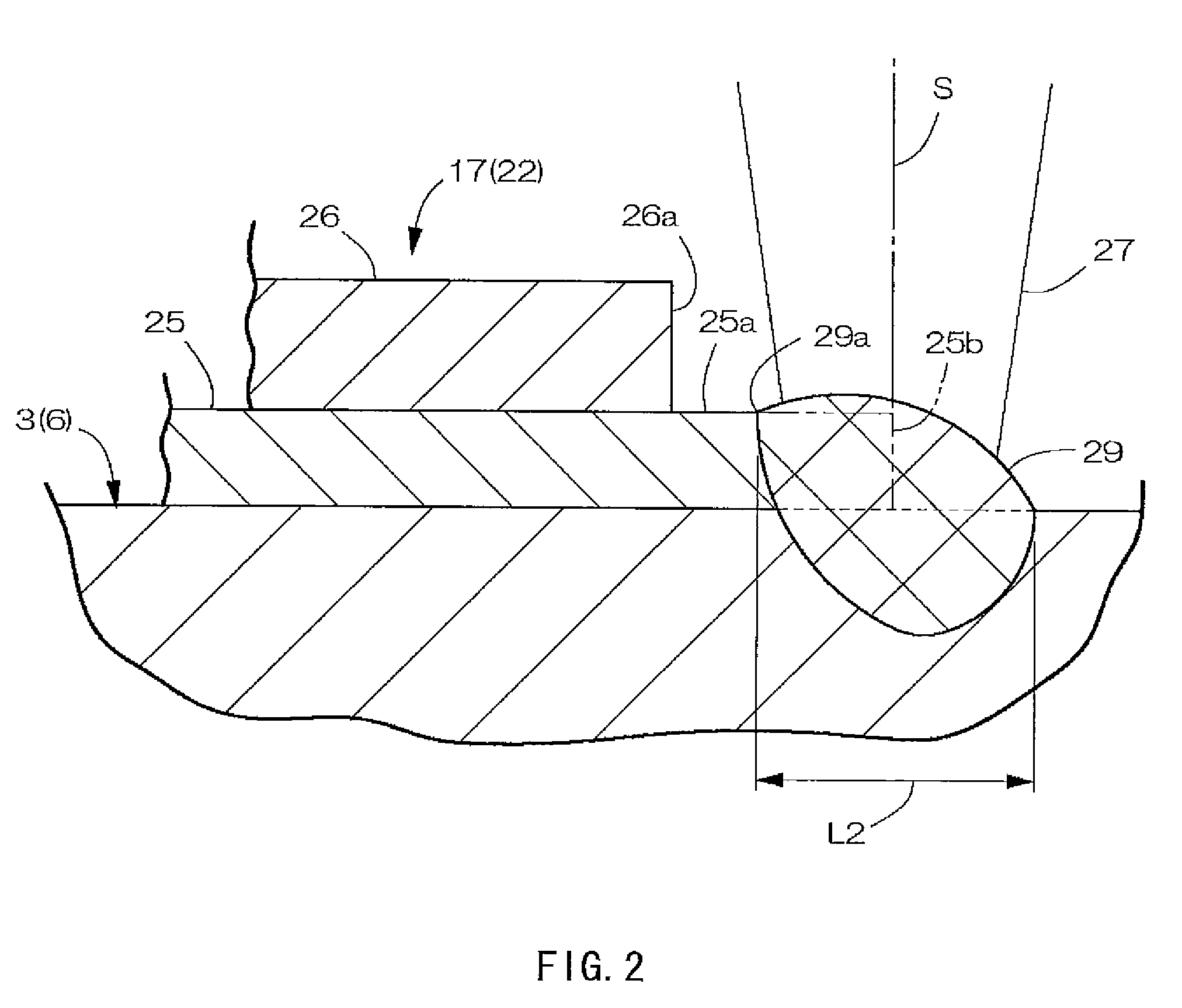
[0049]In the batteries according to Example 1, the seal 17 was welded to the lid 3 in a position in which the central axis S of the laser beam 27 was 0.1 mm closer to the nickel layer 26 side than the outer peripheral edge 25b of the aluminum layer 25 in the head section 22 of the seal 17. Thus, the position of the edge 29a of the welding mark 29 on the nickel layer 26 side coincided with the position of the outer peripheral edge 26a of the nickel layer 26.

Example

Example 2
[0050]In the batteries according to Example 2, the seal 17 was welded to the lid 3 in a position in which the central axis S of the laser beam 27 coincided with the outer peripheral edge 25b of the aluminum layer 25 in the head section 22 of the seal 17. Thus, the position of the edge 29a of the welding mark 29 on the nickel layer 26 side was 0.1 mm to the outside of the position of the outer peripheral edge 26a of the nickel layer 26.

Example

Example 3
[0051]In the batteries according to Example 3, the seal 17 was welded in a position in which the central axis S of the laser beam 27 was 0.2 mm to the outside of the outer peripheral edge 25b of the aluminum layer 25 in the head section 22 of the seal 17. Thus, the position of the edge 29a of the welding mark 29 on the nickel layer 26 side was 0.3 mm to the outside of the outer peripheral edge 26a of the nickel layer 26.
Comparative Example
[0052]In the batteries according to the comparative example, the seal 17 was welded to the lid 3 in a position in which the central axis S of the laser beam 27 was 0.3 mm closer to the nickel layer 26 side than the outer peripheral edge 25b of the aluminum layer 25 in the head section 22 of the seal 17. Thus, the edge 29a of the welding mark 29 on the nickel layer 26 side was positioned 0.1 mm inside the outer peripheral edge 26a of the nickel layer 26, and the welding mark 29 overlapped with the nickel layer 26.
TABLE 1 Number of batteries in which the occurrence of pinholes and spatters was observed (number) Example 1 1 (Only the occurrence of spatters was observed.) Example 2 0 Example 3 0 Comparative Example 10
[0053]As is clear from Table 1, among the batteries of Example 1, the occurrence of pinholes was observed in none of the batteries, and the occurrence of spatters was observed in only one of the batteries. Among the batteries of Examples 2 and 3, the occurrence of pinholes and the occurrence of spatters were not observed. In contrast, among the batteries of the comparative example, the occurrence of pinholes and the occurrence of spatters were observed in ten of the batteries.
[0054]Note that when the position of the central axis S of the laser beam 27 was moved further outward from the position of Example 3, the laser beam 27 no longer impinged on the outer peripheral edge portion 25a of the aluminum layer 25, and the outer peripheral edge portion 25a of the aluminum layer 25 was not welded to the lid 3.
[0055]As described above, since the outer peripheral edge portion 25a of the aluminum layer 25 in the head section 22 of the seal 17 protrudes outward beyond the outer peripheral edge 26a of the dissimilar metal layer 26, the laser beam 27 can be directly irradiated onto the aluminum layer 25, and thus the aluminum layer 25 can be reliably welded to the battery case 6.
[0056]Since the seal 17 is welded by the laser beam 27 so that the edge 29a of the welding mark 29 is positioned outside the outer peripheral edge 26a of the dissimilar metal layer 26, the occurrence of spatters, that is, melting and spattering of the dissimilar metal layer 26 due to heat generated by the laser beam 27 can be prevented, and thus the occurrence of welding defects, such as pinholes, associated with the occurrence of spatters can be prevented.
[0057]The protruding dimension L1 of the outer peripheral edge portion 25a of the aluminum layer 25 of the seal 17 can be increased. However, a protruding dimension L1 of 0.8 mm or more will result in difficulty in pressing. Moreover, the protruding dimension L1 is also limited by the size of the battery and other factors. The protruding dimension L1 is set with consideration given to these matters. As for the diameter of the laser beam 27, when the diameter is increased, the irradiation energy of the laser beam 27 needs to be increased accordingly. On the other hand, when the diameter is too small, the aluminum layer 25 is melted too deeply, resulting in a risk that spattering of the aluminum layer 25 may occur. The diameter of the laser beam 27 is set with consideration given to these matters.
[0058]The shaft section 23 of the seal 17 may also be made of synthetic rubber or the like. In this case, the shaft section 23 is fixed to the lower surface 22a of the head section 22 with an adhesive or the like. The shaft section 23 may also be inserted into the liquid injection hole 16 in a state where the shaft section 23 has some play. Moreover, the shaft section 23 may also be omitted, and the seal 17 may be formed only of the head section 22. Even in this case, the outer peripheral edge portion 25a of the aluminum layer 25 protrudes outside the seal 17 beyond the outer peripheral edge 26a of the dissimilar metal layer 26.
[0059]The liquid injection hole 16 and the seal 17 are not necessarily required to be provided in the lid 3 and can be provided in any part of the battery case 6. For example, the liquid injection hole 16 and the seal 17 may also be provided in the bottom surface or a side surface of the battery can 1.
[0060]In the seal 17, as the dissimilar metal layer 26 there may also be used in addition to nickel or nickel alloy, a metal layer made of stainless steel, a stainless alloy, or the like. The battery can 1 and the lid 3 may also be prepared using a clad material at least the exterior side of which is formed of a layer of aluminum or an aluminum alloy.
[0061]The invention may be embodied in other forms without departing from the spirit or essential characteristics thereof The embodiment disclosed in this application is to be considered in all respects as illustrative and not limiting. The scope of the invention is indicated by the appended claims rather than by the foregoing description, and all changes which come within the meaning and range of equivalency of the claims are intended to be embraced therein.

PUM

no PUM

Description & Claims & Application Information

We can also present the details of the Description, Claims and Application information to help users get a comprehensive understanding of the technical details of the patent, such as background art, summary of invention, brief description of drawings, description of embodiments, and other original content. On the other hand, users can also determine the specific scope of protection of the technology through the list of claims; as well as understand the changes in the life cycle of the technology with the presentation of the patent timeline. Login to view more.
Why Eureka
Try Eureka