
Inkjet recording head and method for manufacturing the same

a technology of recording head and manufacturing method, which is applied in the field of high-precision machining methods of piezoelectric elements, which are suited to linear machining, and can solve the problems of increasing the probability of blasting particles colliding with the sides of the piezoelectric plate, unable to work the piezoelectric ceramic plate (piezoelectric plate) into arbitrary shapes, and not being able to meet the requirements of linear machining

Inactive Publication Date: 2004-06-03
FUJIFILM BUSINESS INNOVATION CORP
View PDF6 Cites 45 Cited by
  • Summary
  • Abstract
  • Description
  • Claims
  • Application Information

AI Technical Summary

Benefits of technology

Facilitates the mass production of inkjet recording heads with high-density, uniformly arranged piezoelectric elements, improving the reliability and quality of ink droplet ejection by preventing side etching and dielectric breakdown, leading to high-quality image output.

Problems solved by technology

These high-precision machining methods for piezoelectric elements, although suited to linear machining, are incapable of working the piezoelectric ceramic plate (piezoelectric plate) into arbitrary shapes.
That is, a larger width of the trenches to be formed along the piezoelectric elements increases the probability for blasting particles to collide with the sides of the piezoelectric plate.
Due to this property of the sandblasting processing, the piezoelectric elements formed at the periphery of the piezoelectric element array suffer from higher side etching.
As a result, the peripheral piezoelectric elements may be deteriorated in the dimensional accuracy.

Method used


Image

  • Inkjet recording head and method for manufacturing the same
  • Inkjet recording head and method for manufacturing the same
  • Inkjet recording head and method for manufacturing the same

Examples


second embodiment

[0091] Second Embodiment

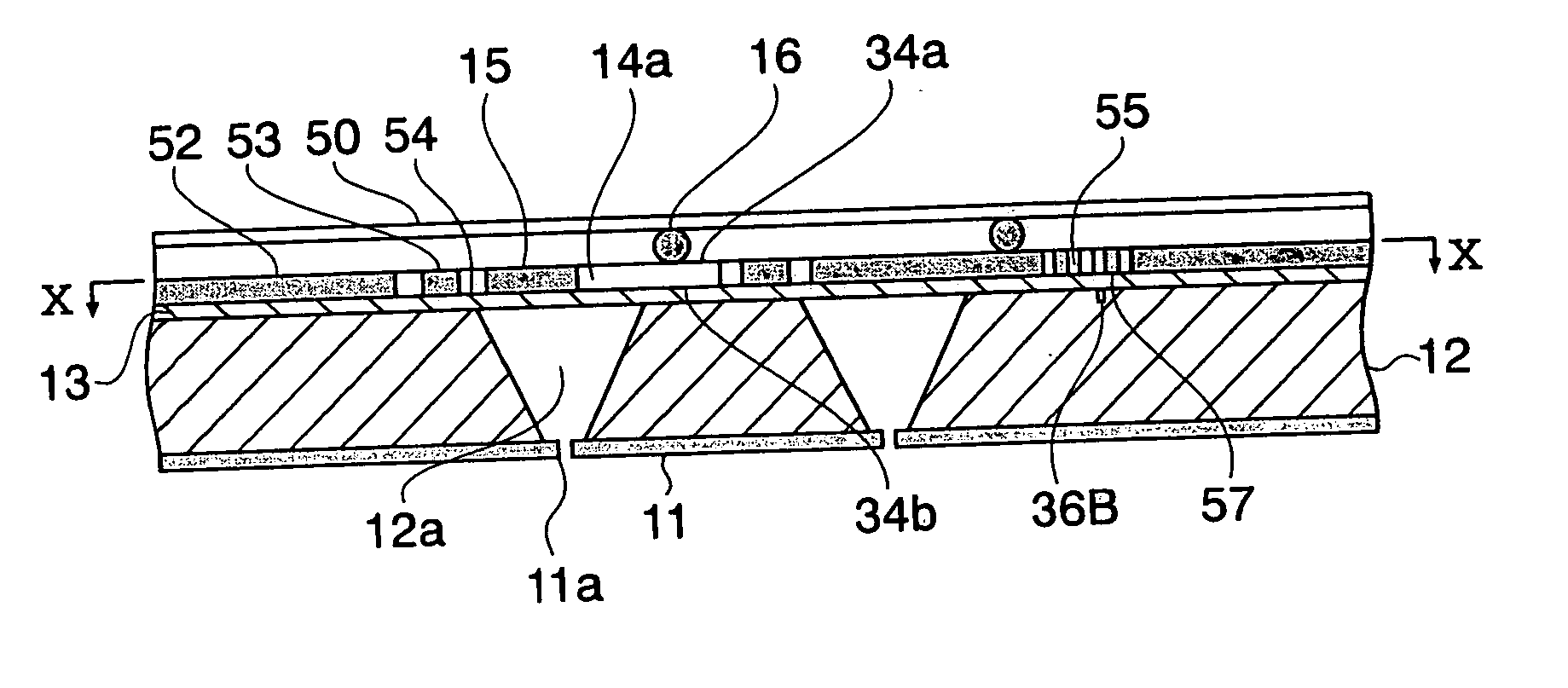
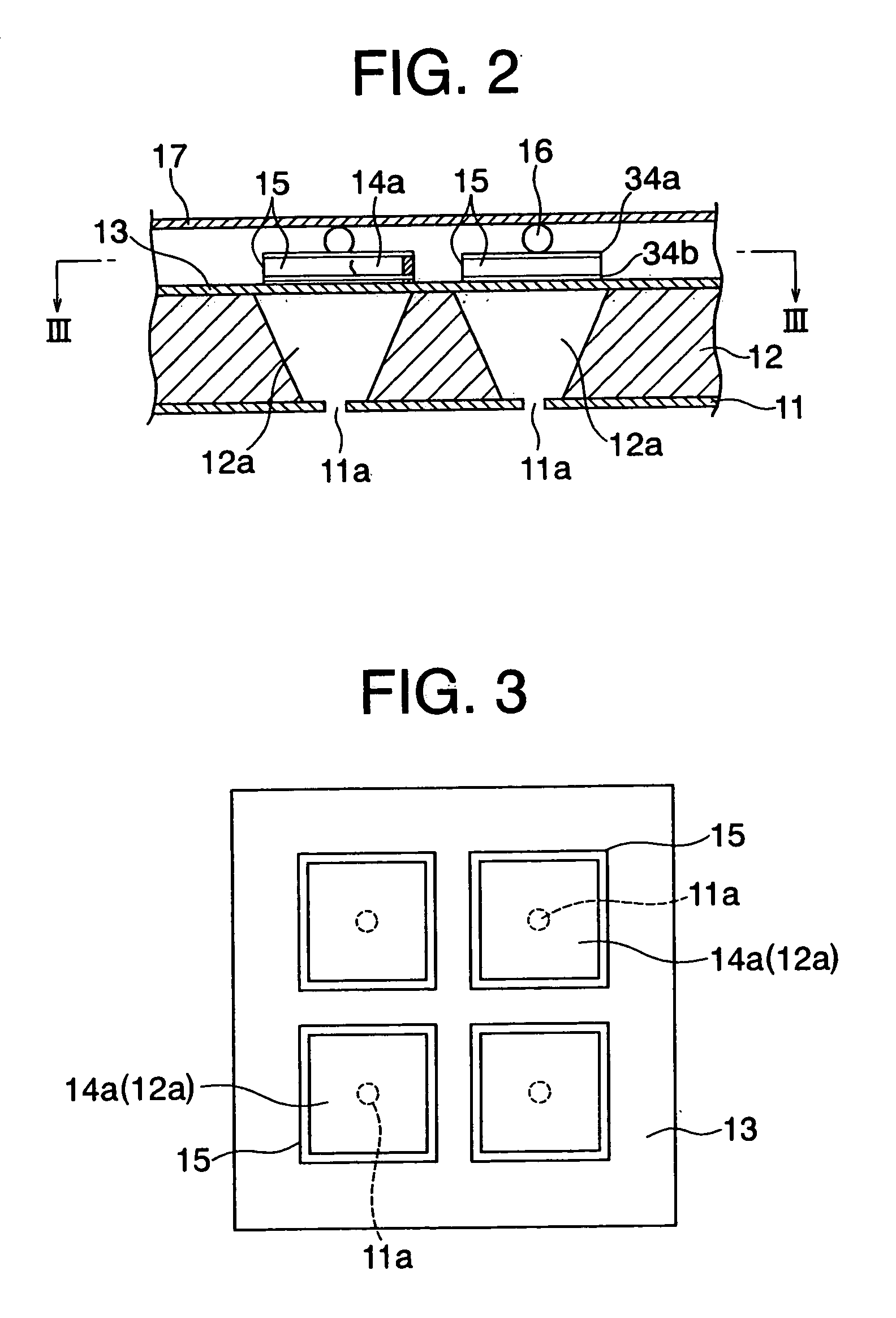
[0092] Now, description will be given of a second embodiment according to the present invention. The present embodiment is directed to an example of the inkjet recording head that includes pressure chambers of square shape and piezoelectric elements having a different, rectangular shape. FIG. 9 is a sectional view showing the configuration of the essential parts of the ink-jet recording head in the present embodiment.

[0093] This inkjet recording head has a nozzle plate 11 in which a plurality of nozzles 11a are formed in a two dimensional array. On this nozzle plate 11 are arranged a pressure chamber plate 12 and a diaphragm 13. The pressure chamber plate 12 defines therein a plurality of pressure chambers 12a each communicating with a corresponding nozzle 11a. The diaphragm 13 is bonded so as to close the pressure chambers 12a.

[0094] A plurality of piezoelectric elements 14a are arranged on the other side of the diaphragm 13 far from the pressure chambers 12...

third embodiment

[0114] Third Embodiment

[0115] FIG. 22 is a perspective view showing an inkjet recording device according to a third embodiment of the present invention. The inkjet recording device 60 of the present embodiment includes a carriage 61, a main scanning mechanism 63, and a sub-scanning mechanism 65. The carriage 61 incorporates an ink-jet recording head according to an embodiment of the present invention. The main scanning mechanism 63 allows the carriage 61 to scan in main scanning directions 66. The sub-scanning mechanism 65 feeds a recording sheet 64, a recording medium, in a direction (sub-scanning direction 67) normal to the main scanning direction.

[0116] The inkjet recording head is mounted on the carriage 61 so that the nozzle surface opposes the recording sheet 64. While moved in the main scanning directions 66, the inkjet recording head ejects ink droplets onto the recording sheet 64 to perform recording over a certain stripe area 68. The recording sheet 64 is then fed in the s...


PUM


Abstract

An inkjet recording head includes a two-dimensional array of a pressure chambers and corresponding array of piezoelectric elements each for applying a pressure wave to ink in a corresponding pressure chamber. In fabrication, a piezoelectric plate temporarily bonded onto a substrate is subjected to sandblasting to form the plurality of piezoelectric elements After the piezoelectric elements are bonded as a unit onto a diaphragm which constitutes part of the walls of the pressure chambers, the substrate is removed. Dummy patterns equalize the degree of side etching among the piezoelectric elements.

Description

[0001] 1. Field of the Invention[0002] The present invention relates to an inkjet recording head, which is capable of incorporation into information equipment such as a word processor, facsimile, and printer, a method for manufacturing the same, and an inkjet recording device. In particular, the present invention relates to an inkjet recording head configured to allow high-density arrangement in a two-dimensional array of piezoelectric elements and facilitate mass production thereof, a method for manufacturing such an ink-jet recording head, and an inkjet recording device having such an inkjet recording head.[0003] 2. Description of the Related Art[0004] In recent years, an impact recording process has attracted much attention for its small noise in recording and a high recording speed thereof. Among other impact recording processes, an inkjet recording process used in inkjet printers has been in wide use. The inkjet printer allows ink droplets to be ejected from the recording head ...

Claims


Application Information

Patent Timeline
Patent Type & Authority Applications(United States)
IPC IPC(8): B41J2/045B41J2/055B41J2/14B41J2/16
CPCB41J2/14233B41J2/161B41J2/1623B41J2/1631B41J2/1632B41J2/1646Y10T29/42B41J2002/14459B41J2002/14491Y10T29/49401Y10T29/49128Y10T29/49126B41J2002/1425
Inventor MITSUHASHI, MASASHIGEUMEHARA, SHIGERU
Owner FUJIFILM BUSINESS INNOVATION CORP
Learn More